1 absolute position detection function, 1 outline of the function, 2 reading absolute data – Yaskawa JAPMC-MC2300 User Manual
Page 273
10.1 Absolute Position Detection Function
10.1.1 Outline of the Function
10-2
10.1 Absolute Position Detection Function
This section explains the Absolute Position Detection Function in the SVA-01 Module.
Refer to Appendix C Fixed Parameter Setting According to Encoder Type and Axis Type on page A-10 together with
this section.
10.1.1 Outline of the Function
The Absolute Position Detection Function detects the position of the machine (axis) even if the power is turned OFF.
This allows it to establish the machine coordinate system automatically and to begin operating automatically without
having to execute the zero point return (ZRET) command after power is turned ON.
Absolute position detection is performed using an absolute encoder built into a Servomotor.
The following are features of the system for detection of the absolute position.
• If eliminates the need for a zero point return after the power is turned ON.
• If eliminates the need for a zero point dog and overtravel limit switch.
Terminology: Absolute Encoder
There are two types of encoders available. An incremental encoder detects position by calculating the zero point difference. An
absolute encoder detects the absolute position relative to a reference position.
The absolute encoder uses a battery connected to the battery terminals of the SERVOPACK to maintain absolute data at all
times even though power is turned OFF. It also updates absolute data if the position changes while the power is OFF.
The absolute encoder is comprised of a detector that is used to detect absolute position within one rotation and a counter that is
used to count the number of rotations.
After the automatic operation starts, the absolute encoder operates in the same way as an incremental
encoder.
10.1.2 Reading Absolute Data
Turn ON the Machine Controller and the SERVOPACK at the same time or turn ON the SERVOPACK first to read the
absolute data loaded from the absolute encoder to the Machine Controller.
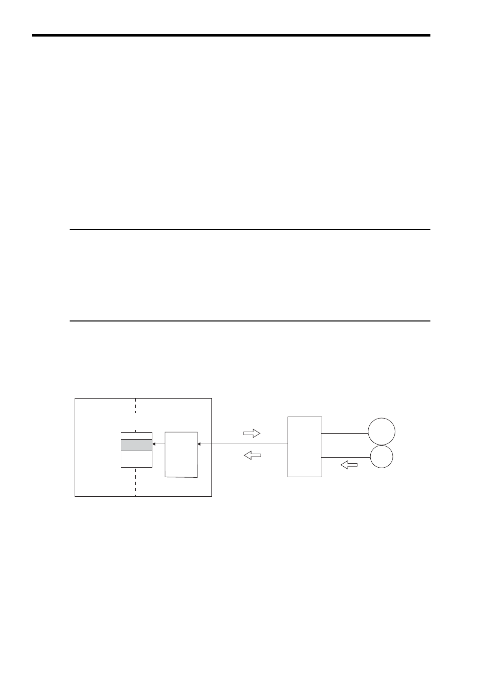
The following diagram shows an overview of the absolute data read operation.
* Refer to 10.3.3 ( 1 ) Calculating the Zero Point of the Machine Coordinate System on page 10-10 for informa-
tion on how to calculate the zero point of machine coordinate system.
Position
monitoring
(IL
0E
to IL
16)
Motion monitoring
parameters
(4)
Electronic
gear
calculation
and
Machine
coordinate
system
calculation
Machine Controller
SERVOPACK
Servomotor
Encoder
(3) Reads absolute data
(N, PO)
(2) Sends absolute data (N, PO)
(1) Requests sensor
initialization
<SVA-01>
(1)
The SVA-01 Module requests SERVOPACK to initialize the sensor when the power supply turns ON.
(2)
SERVOPACK obtains the multiturn data (N) and initial incremental pulses (PO) at reception of the sensor initialization
request from the SVA-01 Module.
(3)
The SVA-01 Module reads out the position data or absolute data from SERVOPACK.
(4)
The SVA-01 Module automatically sets a machine coordinate system
*
according to the electronic gear ratio converted from
the absolute value calculated on the base of the read information and the data of Zero Point Position in Machine Coordinate
System Offset (OL
48).