Yaskawa JAPMC-MC2300 User Manual
Page 181
7.2 Motion Command Details
7.2.3 Zero Point Return (ZRET)
7-41
7
Motion Commands
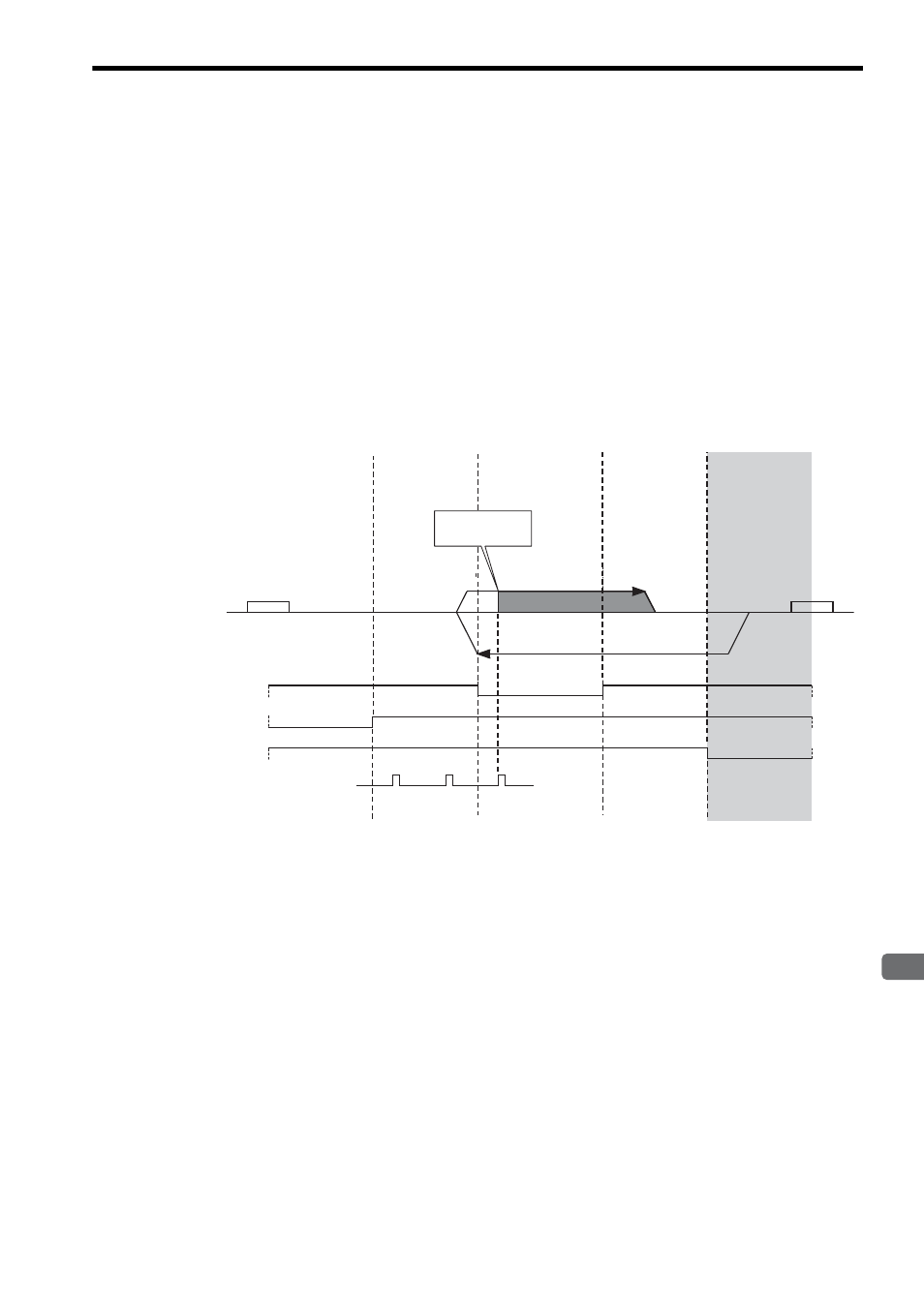
Starting the Zero Point Return in Region E
1.
The axis travels in the reverse direction at the Approach Speed (setting parameter OL
3E).
2.
When the rising edge of the DEC1 signal is detected, the axis decelerates to a stop.
3.
After decelerating to a stop, the axis travels in the forward direction at the Creep Rate (setting parame-
ter OL
40).
4.
After the falling edge of the DEC1 signal is detected, the position is latched when the rising edge of the
first phase-C pulse is detected.
5.
The axis moves from the latched position by the distance set in the Zero Point Return Travel Distance
(setting parameter OL
42) and stops. The machine coordinate system is established with this final
position as the zero point.
If an OT signal is detected during the zero point return operation, an OT alarm will occur.
Zero Point Return Travel Distance
Region A
Region B
Region C
Region D
Region E
Start
DEC1
(DI_5 or OW
05, bit 8)
N-OT
(DI_4)
P-OT
(DI_3)
Approach Speed (OL
3E)
End
Phase-C signal
Phase-C signal
latch at this point
Creep Rate
(OL
40)
Zero Point Return
Reverse Run Side Limit
Signal (OW
05, bit 9)
Zero Point Return
Forward Run Side Limit
Signal
(OW
05, bit 10)