Yaskawa JAPMC-MC2300 User Manual
Page 297
10.4 Absolute Position Detection for Infinite Length Axes
10.4.6 Infinite Length Position Control without Simple Absolute Positions
10-26
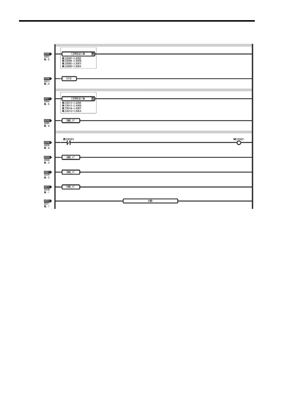
[ b ] Turning the System Back ON (Turning the Servo Back ON)
Set up position data again from the ladder program using high-speed scan timing as shown below. This is done when
Machine Controller power or servo power is turned ON.
1.
Store the pulse position at power OFF and encoder position at power OFF to setting parameters.
Store the pulse position at power OFF and encoder position at power OFF values saved in M register to the fol-
lowing setting parameters.
• Setting parameter: Encoder Position when the Power is OFF (All four words, form OL
5E to OL
60.)
• Setting parameter: Pulse Position when the Power is OFF (All four words, from OL
62 to OL
64.)
Store the contents of the buffer selected by the Toggle Buffer Selection Flag.
2.
Request ABS Rotary Pos. Load bit
Reset the Request ABS Rotary Pos Load bit (setting parameter OW
00, bit 7) to 0, 1 and 0 again. This will
allow all position data to be settled. The following monitoring parameters will then be enabled and the Zero Point
Return (Setting) Completed bit (monitoring parameter IW
0C, bit 5) will turn ON.
• Monitoring Parameter: Encoder Position when the Power is OFF (All four words, from IL
5E to
IL
60.)
• Monitoring Parameter: Pulse Position when the Power is OFF (All four words, from IL
62 to IL
64.)
The system will create position data using the following equation when Request ABS Rotary Pos. Load bit is set
to 1.
• Pulse position = pulse position at power OFF + (encoder position
− encoder position at power OFF)*
* The portion in parentheses ( ) represents the moving amount while power is OFF.
Values of monitoring parameters saved in buffer 0.
Values of monitoring parameters saved in buffer 1.
Toggle Buffer Selection Flag inverted.