Sgda servopack parameter settings, Sgdb servopack parameter settings – Yaskawa JAPMC-MC2300 User Manual
Page 318
11.4 Other Utility Functions
11.4.4 General-purpose DO_2 Signal Selection
11-18
( 3 ) Precautions When Using the General-purpose DO_2 Signal
(Pin No. 12 of CN1/CN2) as a General-purpose Output Signal
Always set the parameters of the connected SERVOPACK as follows when using the general-purpose DO_2 signal
(pin No. 12 of CN1/CN2) as a general-purpose output signal.
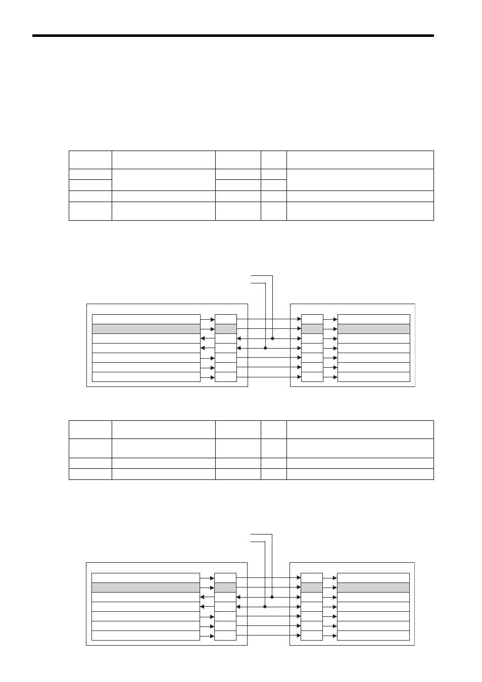
SGDA SERVOPACK Parameter Settings
The following diagram shows a connection example of the SVA-01 Module and the SGDA SERVOPACK input sig-
nals. Refer to 2.5.3 Cable for Connecting a SGDA-
S SERVOPACK on page 2-16.
The general-purpose DO_2 signal (pin No. 12 of CN1/CN2) is connected to the /P-CON signal of the SGDA SERVO-
PACK.
SGDB SERVOPACK Parameter Settings
The following diagram shows a connection example of the SVA-01 Module and the SGDB SERVOPACK input sig-
nals. Refer to 2.5.4 Cable for Connecting a SGDB-
SERVOPACK on page 2-17.
The general-purpose DO_2 signal (pin No. 12 of CN1/CN2) is connected to the /P-CON signal of the SGDB SERVO-
PACK.
Parameter
No.
Name
Default Value
Set
Value
Setting Contents
Cn-01, bit A
Control mode selection
0
0
Speed control
Cn-01, bit B
0
0
Cn-01, Bit F Torque feed forward function
0
0
Disables the torque feed forward function.
Cn-02, bit F Torque reference input selection
0
1
In speed control mode, TREF is used as the torque
limit.
CN1/CN2
General-purpose input N-OT/
General-purpose input P-OT/
SGDA SERVOPACK
CN1
SVA-01 Module
Setting/Monitoring Parameters
Input Signals
/S-ON
OW
00, bit 0: Servo ON
31
14
OW
5D, bit 2: General-purpose DO_2
/P-CON
12
15
IW
58, bit 4: General-purpose DI_4
33
N-OT
17
OW
00, bit 15: Alarm clear
/ALM RST
30
18
IW
58, bit 3: General-purpose DI_3
15
P-OT
16
OW
5D, bit 3: General-purpose DO_3
14
12
/N-CL
OW
5D, bit 4: General-purpose DO_4
13
11
/P-CL
Parameter
No.
Name
Default Value
Set
Value
Setting Contents
Cn-02, bit 8 Analog current limit function
0
1
In speed control mode, TREF is used as the analog
current limit (torque limit).
Cn-02, bit 9 Torque feed-forward function
0
0
Disables the torque feed forward function.
Cn-2B
Control method selection
0
0
Speed control (analog reference)
CN1/CN2
General-purpose input N-OT/
General-purpose input P-OT/
SGDB SERVOPACK
CN1
SVA-01 Module
Setting/Monitoring Parameters
Input Signals
/S-ON
OW
00, bit 0: Servo ON
31
40
OW
5D, bit 2: General-purpose DO_2
/P-CON
12
41
IW
58, bit 4: General-purpose DI_4
33
N-OT
43
OW
00, bit 15: Alarm clear
/ALM RST
30
44
IW
58, bit 3: General-purpose DI_3
15
P-OT
42
OW
5D, bit 3: General-purpose DO_3
14
46
/N-CL
OW
5D, bit 4: General-purpose DO_4
13
45
/P-CL