2 ) encoder resolution – Yaskawa JAPMC-MC2300 User Manual
Page 289
10.4 Absolute Position Detection for Infinite Length Axes
10.4.3 Detailed Descriptions on Parameter Settings for Simple Absolute Infinite Length Axes
10-18
10.4.3 Detailed Descriptions on Parameter Settings for Simple Absolute Infinite
Length Axes
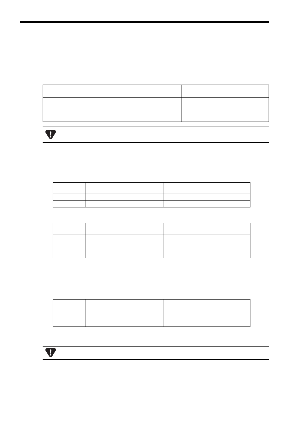
( 1 ) Encoder Selection/Encoder Selection/ Absolute Encoder Usage
For an axis performing absolute position detection, set the parameters as shown in the table below.
( 2 ) Encoder Resolution
The methods to set the fixed parameter No. 36 and No. 22 differs depending on the connected SERVOPACK model.
When a
Σ-I Series SERVOPACK is Connected
When a
Σ-II Series SERVOPACK is Connected
* 1. The actual value depends on the value of Pn201 (PG Divider). The values shown here are the max. values
that can be set for each encoder.
* 2. The set value when using a 17-bit encoder is limited to 16384 max. since the max. value that can be set for
Pn201 (PG Divider) is 16384.
When a
Σ-III or Σ-V Series SERVOPACK is Connected
The actual value depends on the value of Pn212 (PG Dividing Pulse). The values shown here are the max. val-
ues that can be set.
Model
Parameter
Setting
SVA-01 Module
Fixed parameter 30: Encoder Selection
1: Absolute encoder
Σ-II/Σ-III/Σ-V Series
SERVOPACK
Parameter Pn002.2: Absolute Encoder Usage
0: Uses absolute encoder as an absolute encoder
Σ-I Series SERVO-
PACK
Parameter Cn-0001, Bit E: Encoder Selection
1: Absolute encoder
If the above settings are not used, correct motion control will not be performed. Set the parameters carefully.
Be sure to set both the SVA-01 Module and SERVOPACK parameters.
Number of Bits
Fixed Parameter No. 36
Number of Pulses per Motor Rotation
Fixed Parameter No. 22
Pulse Counting Mode Selection
12
1024
6: Pulse A/B mode (Input pulse multiplier: 4)
15
8192
6: Pulse A/B mode (Input pulse multiplier: 4)
Number of Bits
Fixed Parameter No. 36
Number of Pulses per Motor Rotation
Fixed Parameter No. 22
Pulse Counting Mode Selection
13
2048
∗1
6: Pulse A/B mode (Input pulse multiplier: 4)
16
16384
∗1
6: Pulse A/B mode (Input pulse multiplier: 4)
17
16384
∗1, ∗2
6: Pulse A/B mode (Input pulse multiplier: 4)
Number of Bits
Fixed Parameter No. 36
Number of Pulses per Motor Rotation
Fixed Parameter No. 22
Pulse Counting Mode Selection
17
16384
∗
6: Pulse A/B mode (Input pulse multiplier: 4)
20
262144
∗
6: Pulse A/B mode (Input pulse multiplier: 4)
If the above settings are not used, correct motion control will not be performed. Set the parameters carefully.