2 normal operation mode, 2 di/do signals in normal operation mode – Yaskawa JAPMC-MC2300 User Manual
Page 63
4.2 Normal Operation Mode
4.2.1 Motion Parameters That Can be Used in Normal Operation Mode
4-3
4
Operation Modes
4.2 Normal Operation Mode
Set the fixed parameter No. 0 (Selection of Operation Modes) to 0 to select the normal operation mode.
In normal operation mode, the SVA-01 Module is used as an ordinary motion module.
4.2.1 Motion Parameters That Can be Used in Normal Operation Mode
Refer to
5.3 Motion Parameter Lists on page 5-5
for the motion parameters that can be used in normal operation mode.
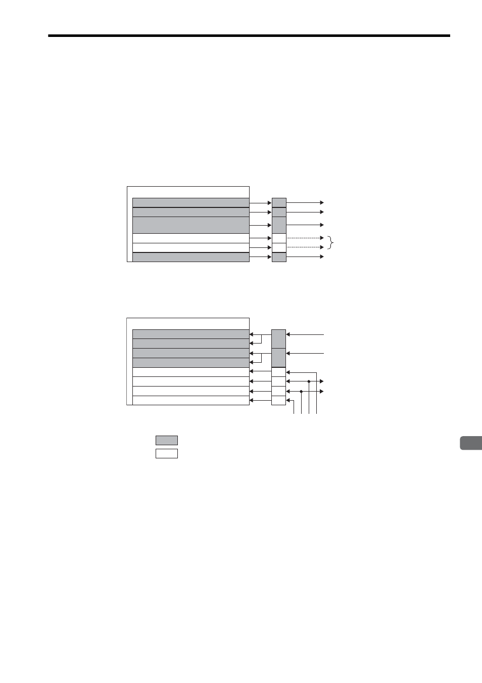
4.2.2 DI/DO Signals in Normal Operation Mode
In normal operation mode, some of DI/DO signals can be used as general-purpose signals as shown below.
Pin No.12 of CN1/CN2 can be used only when the General-purpose DO_2 Signal Selection bit ( fixed parameter
No.21, bit 5) is set to 1(Use as a general-purpose signal). Refer to 11.4.4 General-purpose DO_2 Signal Selection on
page 11-17 for details.
The input signals DI_2 to DI_5 can be used by the user unless they are already used by the system. These signals are
referred to as shared signals.
/S-ON
/ALM RST
/P-CON
(Used as C-SEL signal)
SEM
Selected by the user
OW
00, bit 0:
OW
00, bit 15:
Internal variable:
OW
5D, bit 3:
OW
5D, bit 4:
Internal variable:
I/O Output
Servo ON
Alarm Reset
Control Mode Switching
General-purpose DO_3
General-purpose DO_4
SEN signal
31
30
12
14
13
32
CN1/CN2
/ALM
/S-RDY
/P-OT
/N-OT
IW
04, bit 0:
IW
58, bit 0:
IW
00, bit 3:
IW
58, bit 1:
IW
58, bit 2:
IW
58, bit 3:
I/O Input
Servo Driver Error
General-purpose DI_0
Servo Ready
General-purpose DI_1
General-purpose DI_2 *
General-purpose DI_3
17
35
18
15
IW
58, bit 4:
IW
58, bit 5:
General-purpose DI_4
General-purpose DI_5 *
33
36
CN1/CN2
ZERO/HOME
OTF
OTR
EXT/DEC
: Reserved for the system
: Can be used by the user
Note:
* Can be used as a latch signal.