3 monitoring parameter list – Yaskawa JAPMC-MC2300 User Manual
Page 85
5.3 Motion Parameter Lists
5.3.3 Monitoring Parameter List
5-13
5
Motion Parameters
5.3.3 Monitoring Parameter List
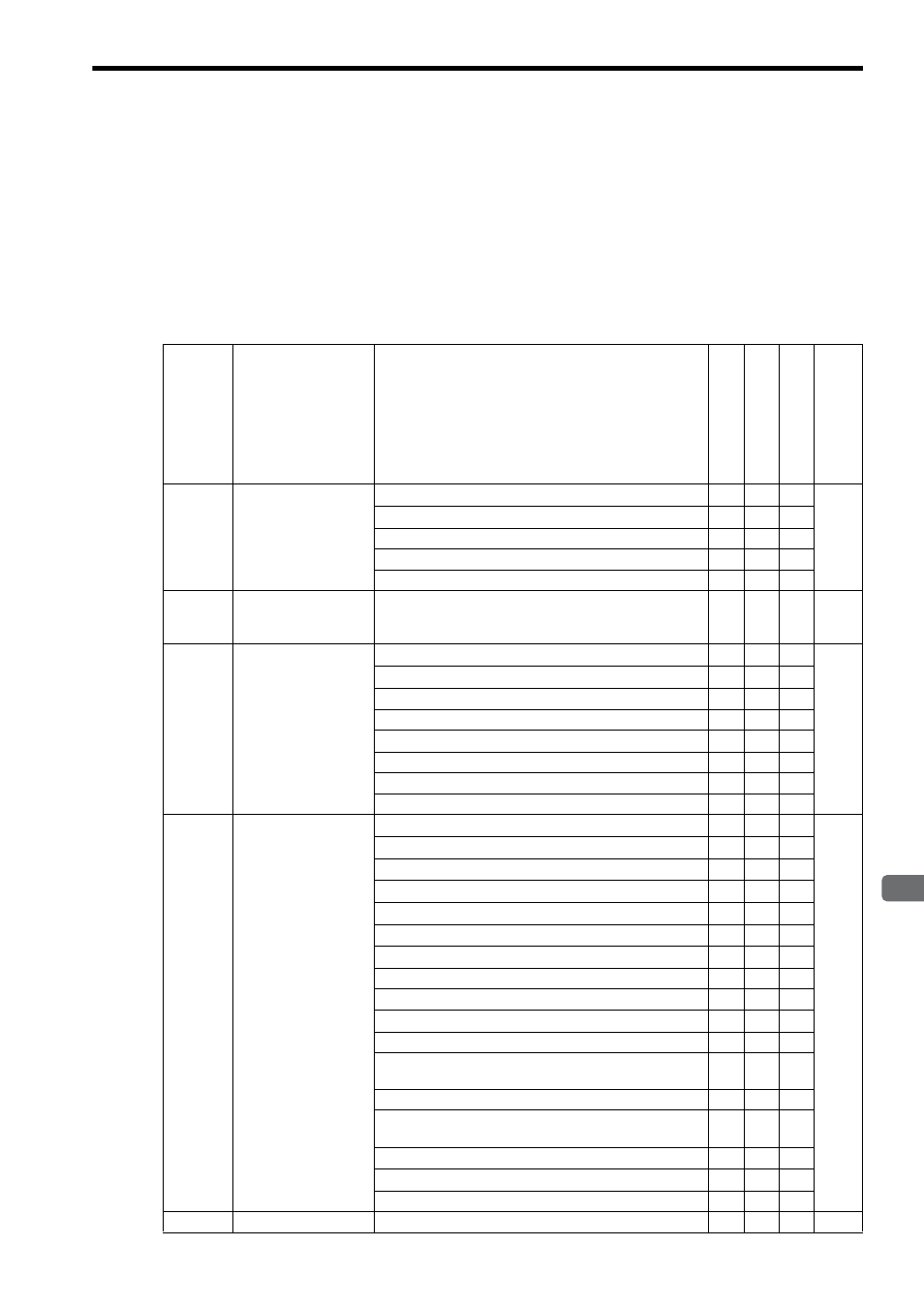
The following table provides a list of SVA motion monitoring parameters.
The register number “IW
00” indicates the leading input register number + 00. Refer to 5.1.1 Motion Parameter
Register Numbers for MP2000 Series Machine Controllers on page 5-2 for information on how to obtain the leading
input register number.
The commands marked with in the Normal Operation Mode, Simulation Mode, and General-purpose I/O Mode
columns can be used in the corresponding operation mode. The operation mode can be selected by setting the fixed
parameter No. 0 (Selection of Operation Modes) to 0 for normal operation mode, to 2 for simulation mode, or to 4 for
general-purpose I/O mode.
Refer to the pages listed in the Reference Page for details of each monitoring parameter.
Register
No.
Name
Description
Normal Op
erat
ion Mod
e
Simu
lat
ion Mode
Ge
neral
-purp
ose I/
O Mode
Refer-
ence
Page
IW
00 RUN Status
Bit 0: Motion Controller Operation Ready
P.5-43
Bit 1: Running (Servo ON)
Bit 2: Reserved for system use
-
-
-
Bit 3: Servo Ready
Bits 4 to F: Reserved for system use
-
-
-
IW
01
Parameter Number
when Range Over is
Generated
Setting parameters: 0 or higher
Fixed parameters: 1000 or higher
P.5-43
IL
02
Warning
Bit 0: Excessive Deviation
P.5-44
Bit 1: Set Parameter Error (Setting parameter error)
Bit 2: Fixed Parameter Error
Bit 3: Reserved for system use
-
-
-
Bit 4: Motion Command Set Error
Bits 5 to A: Reserved for system use
-
-
-
Bit B: Analog Adjust Not Ready Warning
Bits C to 1F: Reserved for system use
IL
04
Alarm
Bit 0: Servo Driver Error
P.5-45
Bit 1: Positive Direction Overtravel
Bit 2: Negative Direction Overtravel
Bit 3: Positive Direction Software Limit
Bit 4: Negative Direction Software Limit
Bit 5: Servo OFF
Bit 6: Positioning Time Over
Bit 7: Reserved for system use
-
-
-
Bit 8: Excessive Speed
Bit 9: Excessive Deviation
Bits A to C: Reserved for system use
-
-
-
Bit D: Zero Point Unsetting
Invalid for linear type
Bit E to 12: Reserved for system use
-
-
-
Bit 13: Excessive ABS Encoder Rotations
Invalid for linear type
Bit 14: PG Disconnection Error
Bit 15: ABS Total Rev. Receive Error
Bits 16 to 1F: Reserved for system use
-
-
-
IL
06
-
Reserved for system use
-
-
-
-