Yaskawa JAPMC-MC2300 User Manual
Page 68
4.4 General-purpose I/O Mode
4.4.2 Correspondence Between Motion Parameter and Connector Pin Number
4-8
4.4.2 Correspondence Between Motion Parameter and Connector Pin Number
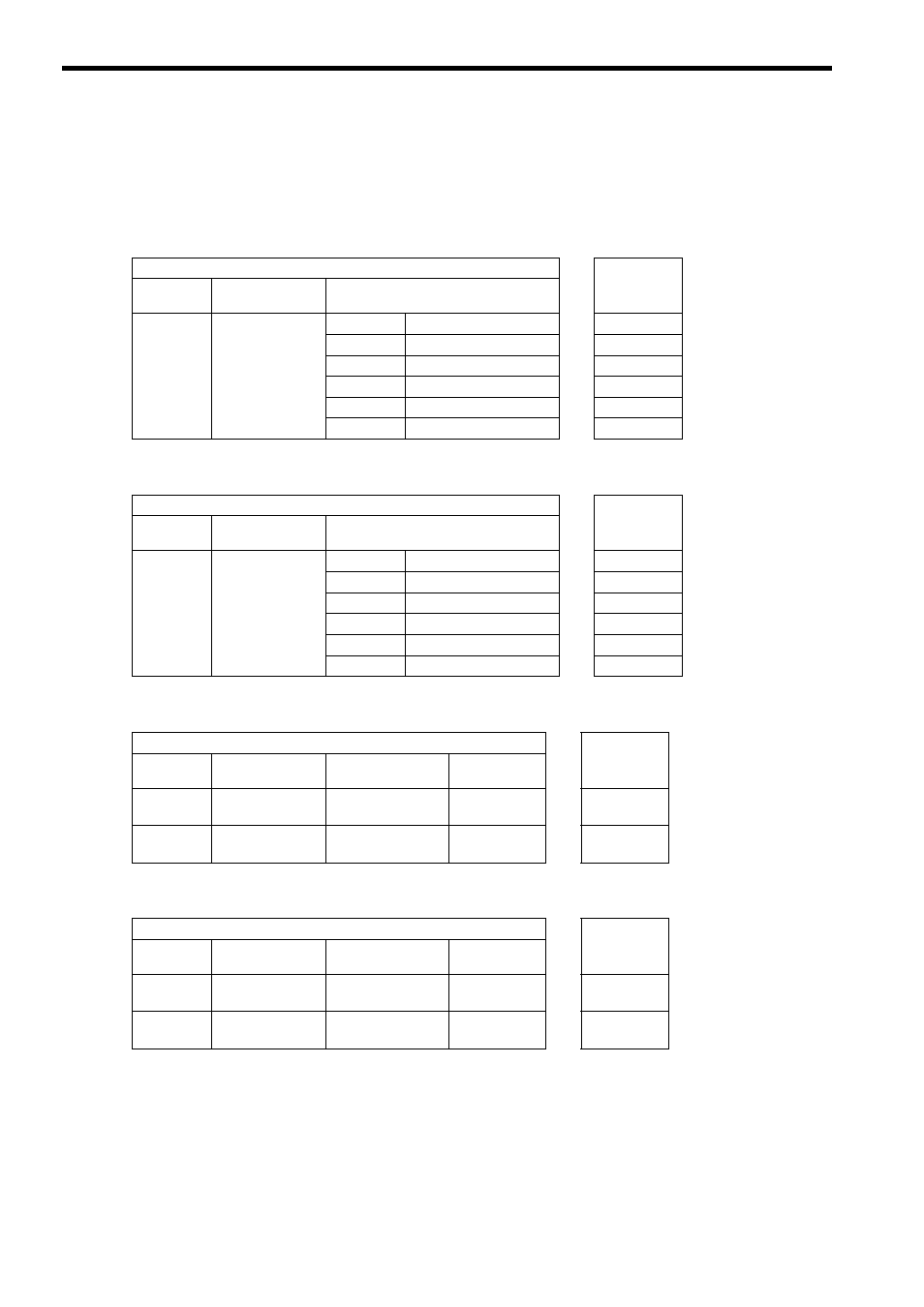
Each motion parameter for general-purpose DO/DI and AO/AI corresponds to the connector pin number as shown
below.
General-purpose DO Outputs (6 Points/Axis)
General-purpose DI Inputs (6 Points/Axis)
General-purpose AO Outputs (2 Channels/Axis)
General-purpose AI Inputs (2 Channels/Axis)
Setting Parameter
CN1/CN2
Pin No.
Register
No.
Name
Description
OW
5D
General-purpose
DO
Bit 0
General-purpose DO_0
→
31
→ Output
Bit 1
General-purpose DO_1
→
30
→ Output
Bit 2
General-purpose DO_2
→
12
→ Output
Bit 3
General-purpose DO_3
→
14
→ Output
Bit 4
General-purpose DO_4
→
13
→ Output
Bit 5
General-purpose DO_5
→
32
→ Output
Monitoring Parameter
CN1/CN2
Pin No.
Register
No.
Name
Description
IW
58
General-purpose
DI
Bit 0
General-purpose DI_0
←
17
← Input
Bit 1
General-purpose DI_1
←
35
← Input
Bit 2
General-purpose DI_2
←
18
← Input
Bit 3
General-purpose DI_3
←
15
← Input
Bit 4
General-purpose DI_4
←
33
← Input
Bit 5
General-purpose DI_5
←
36
← Input
Setting Parameter
CN1/CN2
Pin No.
Register
No.
Name
Setting Range
Setting Unit
OW
1A
General-purpose
AO1
−32768 to 32767
1 = 0.001 V
→
2
→ Output
OW
1B
General-purpose
AO2
−32768 to 32767
1 = 0.001 V
→
9
→ Output
Setting Parameter
CN1/CN2
Pin No.
Register
No.
Name
Setting Range
Setting Unit
IW
59
General-purpose
AI Monitor 1
−32768 to 32767
1 = 0.001 V
←
8
← Input
IW
5A
General-purpose
AI Monitor 2
−32768 to 32767
1 = 0.001 V
←
21
← Input