3 analog servo alarm list – Yaskawa JAPMC-MC2300 User Manual
Page 351
12.4 Troubleshooting Motion Errors
12.4.3 Analog Servo Alarm List
12-32
12.4.3 Analog Servo Alarm List
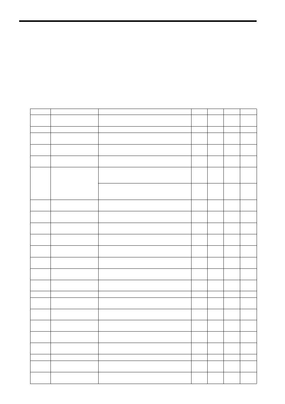
The Servo Driver Error Flag (IL
04, bit 0) turns ON when an alarm has occurred in a SERVOPACK connected to
the SVA-01 Module.
The content of the alarm can be confirmed by connecting a Digital Operator to the SERVOPACK.
The following tables show the alarms that can occur in the SGDA, SGDB, SGDM, SGDH, and SGDS SERVOPACKs.
( 1 ) Alarm List for the SGDA, SGDB, SGDM, and SGDH SERVOPACKs
: Alarm displayed
×: No alarm displayed
Code
Alarm Name
Alarm Content
SGDA
SGDB
SGDM
SGDH
A.00
Absolute Value
Data Error
Absolute data cannot be received or the received abso-
lute data is invalid.
×
×
A.02
Parameter Corrupted
A parameter checksum error was detected.
A.03
Main Circuit Detector
Error
There was an error in the power circuit's detection
data.
×
×
A.04
Parameter Setting
Error
A parameter value setting exceeded the allowed set-
ting range.
A.05
Combination Error
The motor and SERVOPACK capacity settings are
incompatible.
×
×
A.09
Divider Setting Error
An invalid Divider Setting (Pn212) was set (between
increments) or the setting exceeds the connected
Encoder's resolution.
×
×
×
When a linear motor is connected, the setting exceeds
the maximum dividing ratio (Pn281), which was cal-
culated from the linear motor's maximum speed.
×
×
×
A.0A
Encoder Type
Mismatch
A serial encoder has been mounted that is not sup-
ported by the
Σ-II.
×
×
×
A.10
Overcurrent or
Heat Sink Overheat
There was an overcurrent in the power transistor.
The heat sink overheated (SGDM).
A.30
Regeneration Error
An error occurred in the regeneration processing cir-
cuit.
A.31
Position Error Pulse
Overflow
The position error pulses exceeded the “Overflow”
limit set in the parameters.
×
×
A.32
Regeneration
Overload
The regenerative energy exceeds the regenerative
resistor's capacity.
×
×
A.33
Main Circuit Wiring
Error
The power supply method used to supply the main cir-
cuit does not match the setting in parameter Pn001.
×
×
A.40
Overvoltage
The power supply voltage to the main circuit is exces-
sively high.
A.41
Undervoltage
The power supply voltage to the main circuit is too
low.
×
×
A.51
Overspeed
The motor's speed is too high.
A.70
Overload
The torque exceeded the rated torque (high or low
load).
×
×
×
A.71
Overload (High Load)
The torque significantly exceeded the rated torque for
several seconds to several dozen seconds.
×
A.72
Overload (Low Load)
The motor is operating continuously at a torque
exceeding the rated torque.
×
A.73
DB Overload
During dynamic braking operation, the rotating energy
exceeds the DB resistor's capacity.
×
×
A.74
Inrush Resistance Over-
load
The main circuit power supply was turned OFF and
ON repeatedly.
×
×
A.7A
Heat Sink Overheat
The SERVOPACK’s heat sink overheated.
×
×
A.80
Absolute Encoder
Error
The “Number of Pulses per Absolute Encoder Rota-
tion” value is incorrect.
×
×
A.81
Absolute Encoder
Backup Error
The encoder power supplies are all down and the posi-
tion data was cleared.