Yaskawa JAPMC-MC2300 User Manual
Page 283
10.3 Absolute Position Detection for Finite Length Axes
10.3.3 Setting the Zero Point for a Finite Length Axis
10-12
Method 2: Saving in an M Register with a Ladder Program
Saves the value of the zero point offset for the machine coordinate system when the zero point is set in an M register
backed up by a battery. When the power to the Machine controller is turned ON, saves the value of the M register in the
Zero Point Position in Machine Coordinate System Offset for the Machine Coordinate System.
Create a ladder program that automatically executes the following sequence.
Program Example
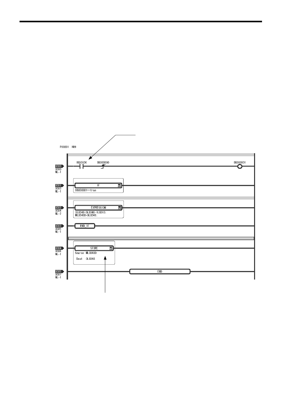
The following diagram shows an example of a ladder program used to store the offset value of axis 1 of line number 1.
In a ladder program for an actual application, select a register with a different address for each axis.
The ladder program shown here is used to carry out the following processing.
• Subtracts the Calculated Position in Machine Coordinate System (IL
10) from the Zero Point Position in
Machine Coordinate System Offset (OL
48) for the Machine Coordinate System and saves the result in
OL
48 after setting the zero point. This value is also saved in an M register at the same time.
• Saves the offset value saved in the M register and in OL
48 after setting the zero point position.
Main Program
Rising edge of Zero Point Set signal detected.
Zero Point Offset - Calculated Position Store in OLoo48.
Store offset saved in M register in OL
48.
Signal that turns ON only when setting the Machine
Execute every scan in high-speed drawing.
Coordinate System Zero Point
(The diagram below shows an example of external signal. The
register number mentioned here has no meaning.)