Yaskawa JAPMC-MC2300 User Manual
Page 45
2.6 Restrictions for Feedback Pulse Inputs
2.6.2 Restrictions in SVA-01 Module Pulse Input Frequency
2-19
2
Settings and Installation
2.6.2 Restrictions in SVA-01 Module Pulse Input Frequency
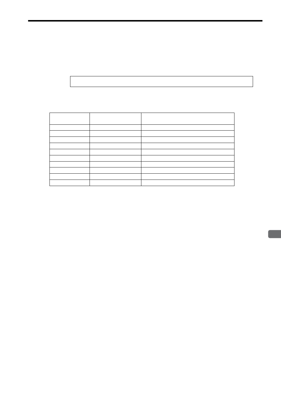
The upper limit to the SVA-01 Module pulse input frequency is shown below.
Upper Limit (actual value) to the SVA-01 Module Phase-A/B Input Pulse Frequency =
4 MHz (before multiplication)
The following table shows the relationship between the number of encoder bits and the maximum speed for a pulse
input frequency of 4 MHz to the SVA-01 Module. Application must be within the range shown in the table when input-
ting pulses to the SVA-01 Module.
* The above table is used to explain restrictions in the SVA-01 pulse input frequency. It contains some numbers of bits
and motor speeds that do not actually exist on the products.
Therefore,
Motor Speed at a Pulse Input Frequency of 4 MHz = 4
× 10
6
× 60 ÷ Encoder resolution
Encoder Bits
*
Encoder Resolution
(before multiplication)
Motor Speed (min
-1
)
*
at a Pulse Input Frequency of 4 MHz
12Bit
1024
234375
13Bit
2048
117187
15Bit
8192
29296
16Bit
16384
14648
17Bit
32768
7324
18Bit
65536
3662
19Bit
131072
1831
20Bit
262144
915
21Bit
524288
457
22Bit
1048576
228