Yaskawa JAPMC-MC2300 User Manual
Page 94
5.4 MP2000 Series Machine Controller Parameter Details
5.4.1 Motion Fixed Parameter Details
5-22
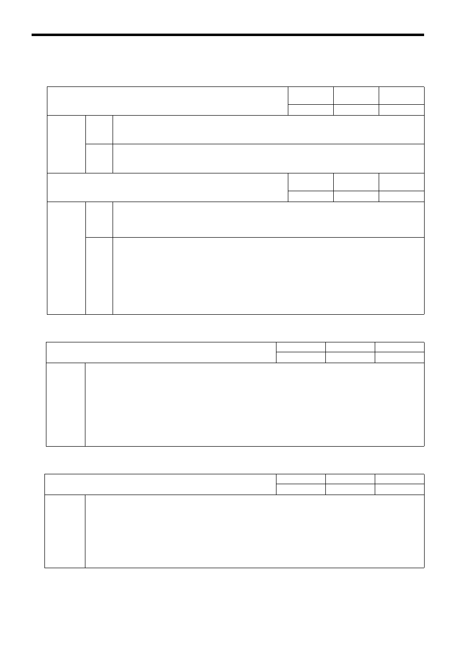
( 8 ) Hardware Signal
( 9 ) Pulse Count
( 10 ) D/A Output
No. 20
Hardware Signal Selection 1
Setting
Range
Setting Unit
Default Value
−
−
0000H
Description
Bit 0
A/B Pulse Input Signal Polarity Selection
0: Positive logic (default)
1: Negative logic
Bit 1
C Pulse Input Signal Polarity Selection
0: Positive logic (default)
1: Negative logic
No. 21
Hardware Signal Selection 2
Setting
Range
Setting Unit
Default Value
−
−
0000H
Description
Bit 0
Deceleration LS Signal Selection
Select a signal to be used for DEC1.
0: Use the setting parameter Zero Point Return Deceleration LS Signal (OW
05, bit 8). (default)
1: Use DI_5 signal.
Bit 5
General-Purpose DO_2 Signal Selection
In normal operation mode, set whether or not to use a general-purpose DO_2 signal as a general-purpose output
signal. When setting this bit to 1 (Use as a general-purpose signal) and using the General-Purpose DO_2 bit (set-
ting parameter OW
5D,bit 2), the user can directly control the general-purpose DO_2 signal (pin No.12 of
CN1/CN2).
0: Use as a system exclusive signal (default).
1: Use as a general-purpose signal.
The parameter settings of the SERVOPACK to be used are required when setting this bit to 1. Refer
to 11.4.4 General-purpose DO_2 Signal Selection on page 11-17 for details.
No. 22
Pulse Counting Mode Selection
Setting Range
Setting Unit
Default Value
0 to 6
−
6
Description
Select one of the following pulse count mode.
0: Sign mode
∗1
1: Sign mode
∗2
2: Up/Down mode
∗1
3: Up/Down mode
∗2
4: A/B mode
∗1
5: A/B mode
∗2
6: A/B mode
∗4
Set to 6: A/B mode (
∗4) when connecting SVA-01 Module to a SERVOPACK.
No. 23
D/A Output Voltage at 100% Speed
Setting Range
Setting Unit
Default Value
1 to 10000
0.001 V
6000
Description
Set the D/A output voltage at 100% speed reference.
Normally, set the servo drive input voltage at the rated speed. Set the value according to the specifications of servo drive
to be used.
D/A output value =
Speed Reference Setting (OL
10)
×
D/A Output Voltage at 100% Speed (fixed parameter no. 23)/10000
<Example>
Where D/A Output Voltage at 100% Speed = 6V, and Speed Reference Setting (OL
10) = 100%
(10000
× 6 V)/10000 = 6 V. Therefore, 6 V is output.