4 ) timing charts – Yaskawa JAPMC-MC2300 User Manual
Page 202
7.2 Motion Command Details
7.2.5 Latch (LATCH)
7-62
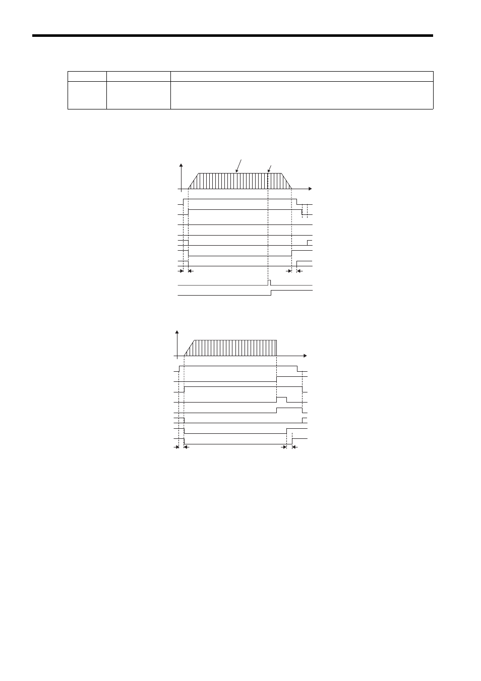
( 4 ) Timing Charts
[ a ] Normal Execution
[ b ] Execution when an Alarm Occurs
IL
18
Machine Coordi-
nate System Latch
Position
Stores the current position in the machine coordinate system when the latch signal turned
ON.
Parameter
Name
Monitor Contents
OW
08 = 6 (LATCH)
IW
08 = 6 (LATCH)
IW
09, bit 0 (BUSY)
Undefined length of time
IW
09, bit 3 (FAIL)
IW
0C, bit 0 (DEN)
1 scan
Latch signal
(EXT (DI_5), ZERO (DI_2), or
phase-C pulse signal)
IW
0C, bit 2 (LCOMP)
The target position is refreshed every high-speed scan.
This position is stored in IL
18.
IW
09, bit 8 (COMPLETE)
IW
0C, bit 1 (POSCOMP)
Alarm
Undefined length of time
IW
0C bit 1 (POSCOMP)
1 scan
OW
08 = 6 (LATCH)
IW
08 = 6 (LATCH)
IW
09 bit 0 (BUSY)
IW
09 bit 8 (COMPLETE)
IW
09 bit 3 (FAIL)
IW
0C bit 0 (DEN)