Yaskawa JAPMC-MC2300 User Manual
Page 184
7.2 Motion Command Details
7.2.3 Zero Point Return (ZRET)
7-44
Parameters to be Set
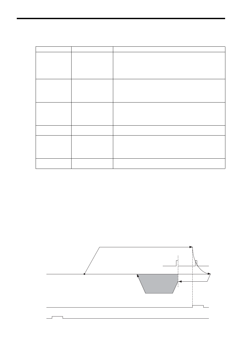
[ j ] P-OT & Phase-C Pulse Method (OW
3C = 12)
Operation after Zero Point Return Starts
Travel is started at the approach speed in the positive direction until the stroke limit is reached.
When the P-OT signal is detected, the direction is reversed to return at creep speed.
When the phase-C pulse is detected during the return after passing the P-OT signal, the positioning is performed.
When the positioning has been completed, a machine coordinate system is established with the final position as the
zero point.
The moving amount after the phase-C pulse is detected is set in the Zero Point Return Travel Distance. The posi-
tioning speed is set in the Speed Reference Setting.
If a negative value is set for the approach speed, the command will end in an error.
If an OT signal is detected during the positioning speed operation, an OT alarm will occur.
The stopping method when the OT signal is detected depends on the setting of SERVOPACK parameters.
Parameter
Name
Setting
OW
03,
Bits 0 to 3
Speed Unit Selection
Select the setting unit for OL
10 (Speed Reference Setting) and
OL
40 (Creep Rate).
0: Reference unit/s
1: 10
n
reference units/min
2: Percentage of rated speed (1 = 0.01%)
3: Percentage of rated speed (1 = 0.0001%)
OL
10
Speed Reference
Setting
Set the positioning speed to use after detecting the phase-C pulse. The sign
is ignored.
The travel direction will depend on the sign of the Zero Point Return Travel
Distance.
Setting to 0 or a negative value will result in an error.
OW
18
Override
This parameter allows the travel speed to be changed without changing the
Speed Reference Setting (OL
10). The setting can be changed during
operation.
Setting range: 0 to 32767 (0 to 327.67%)
Setting unit: 1 = 0.01% (Example) Setting for 50%: 5000
OW
3C
Zero Point Return
Method
11: C Pulse Only Method
OL
40
Creep Rate
Set the speed and travel direction (sign) to use when starting a zero point
return.
The setting cannot be changed during operation. The speed and travel direc-
tion (sign) at the operation start is applied.
Setting to 0 will result in an error.
OL
42
Zero Point Return Travel
Distance
Set the travel distance from the point where a phase-C pulse is detected.
The travel direction will depend on the sign.
Phase-C pulse
N-OT (DI_4)
P-OT (DI_3)
Start
Zero Point
Approach Speed
(OL
3E)
Zero Point Return
Travel Distance
(OL
42)
Speed Reference Setting
(OL
10)
Creep Rate
(OL
40)