1 external appearance and led indicators, 1 external appearance, 2 led indicators – Yaskawa JAPMC-MC2300 User Manual
Page 28
2.1 External Appearance and LED Indicators
2.1.1 External Appearance
2-2
2.1 External Appearance and LED Indicators
2.1.1 External Appearance
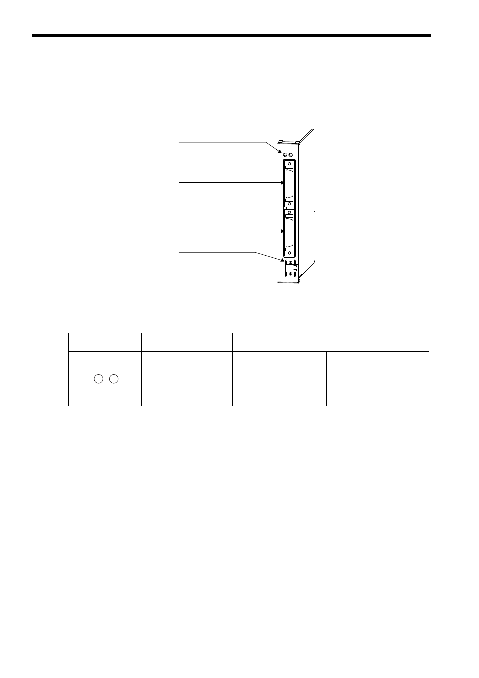
The following figure illustrates the external appearance of the SVA-01 Module.
2.1.2 LED Indicators
The following table shows the indicators that show the operating status of the SVA-01 Module and error information.
SVA-01
LED indicators
CN1: Servo connector
CN3: 24-V input connector
RUN
CH1
CH2
DC IN
ON
+24V
ERR
CN2: Servo connector
Indicators
Indicator
Name
Color
Signification When Lit
Signification When Unlit
RUN Green
Lights during normal operation
of the microprocessor used for
control.
An error has occurred in the micro-
processor for control.
ERR Red
Lights/blinks for failures.
Not lit during normal opera-
tion.
Normally operating
RUN
ERR