Control block diagram, Servopack – Yaskawa JAPMC-MC2300 User Manual
Page 271
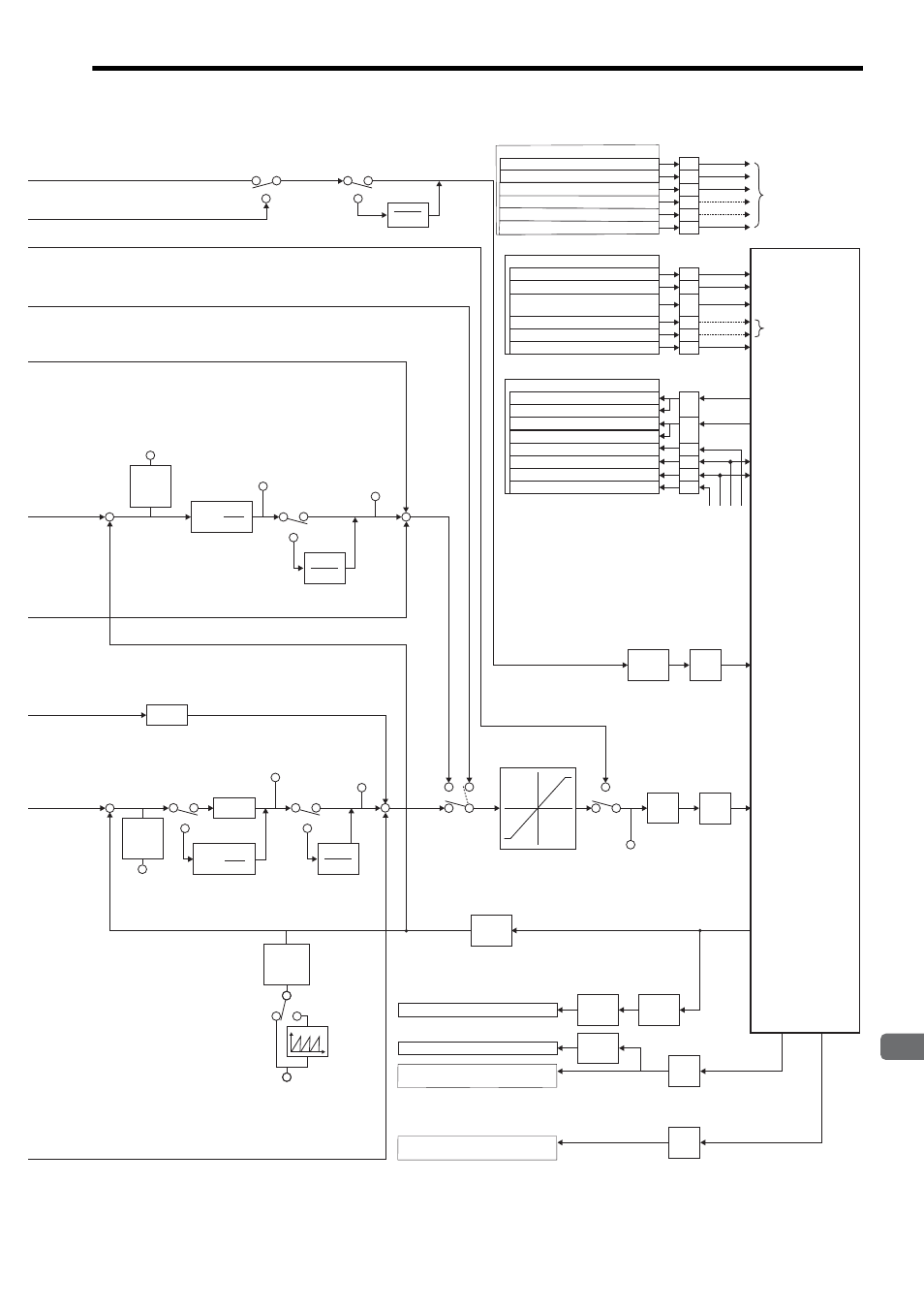
9.1 SVA-01 Module Control Block Diagram
9-3
9
Control Block Diagram
PERR
IL
1A
IL
40: Feedback Speed
IL
42: Feedback Torque/Thrust
IW
5A:
General-purpose AI Monitor 2
[0.001 V]
IW
59:
General-purpose AI Monitor 1
[0.001 V]
Unit
conversion
[pulse]
↓
[UNIT]
PERR
IL
1A
-
-
Unit
conversion
[pulse]
↓
[UNIT]
Unit
conversion
[pulse]
↓
[UNIT]
APOS
IL
16
Finite
length
Infinite
length
General-purpose
outputs
/S-ON
/ALM RST
/ALM
/S-RDY
/P-OT
/N-OT
/P-CON
(Used as C-SEL signal)
SEM
To be selected by the
user
≠TRQ
TRQ
Torque Reference
1st-order Lag Filter
OW
0F
=0
≠0
Primary Lag
1
1+T S
1
Ti S
Integral Output
Monitor
IL
24
Kp (1+ )
1st-order Lag
Time Constant
OW
33
Position Loop
Output Monitor
IL
28
Position
Loop
Output
Monitor
IL
28
=0
≠0
Primary Lag
1
1+T S
PI calulation
Integration reset
with OW
00, bit 11 = ON
or Ti = 0
+
+
+
+
Speed Feedforward Amends
OW
30
=0
≠0
=0
≠0
Integral
Output
Monitor
IL
24
1st-order
Lag
Time
Constant
OW
33
1
Ti S
Kp (1+ )
Integration reset with
OW
00, bit 1 = ON or
Ti = 0
Kf
Kp
Primary Lag
1
1+T S
Position
Integration
Time
Constant
OW
32
Position
Loop
Gain
OW
2E
P control
PHASE
VELO
POSING
EX_POSING
ZRET
INTERPOLATE
LATCH
FEED
STEP
OW
12
OW
13
0
Speed Limiter
≠TRQ
TRQ
Speed Reference
Output Monitor
IL
20
Torque
calculation
Analog
Torque
Reference
Output
D/A
Speed
calcu-
lation
Analog
Speed
Reference
Output
D/A
Current
position
calculation
Feedback
pulse input
Speed
calculation
Moving
average
Torque
calculation
Analog
Torque Monitor Input
A/D
Analog
Speed Monitor Input
A/D
SERVOPACK
PI control
OW
00, bit 0:
OW
00, bit 15:
Internal variable:
OW
5D, bit 3:
OW
5D, bit 4:
Internal variable:
I/O Outputs (In Normal Run Mode)
Servo ON
Alarm Clear
Control Mode
Switching
General-purpose DO_3
General-purpose DO_4
SEN Signal
31
30
12
14
13
32
CN1/CN2
OW
5D, bit 0:
OW
5D, bit 1:
OW
5D, bit 2:
OW
5D, bit 3:
OW
5D, bit 4:
OW
5D, bit 5:
I/O Outputs (In General-purpose I/O Mode)
General-purpose DO_0
General-purpose DO_1
General-purpose DO_2
General-purpose DO_3
General-purpose DO_4
General-purpose DO_5
31
30
12
14
13
32
CN1/CN2
IW
04, bit 0:
IW
58, bit 0:
IW
00, bit 3:
IW
58, bit 1:
IW
58, bit 2:
IW
58, bit 3:
I/O Inputs
Servo Driver Error
General-purpose DI_0
Servo Ready
General-purpose DI_1
General-purpose DI_2*
General-purpose DI_3
17
35
18
15
IW
58, bit 4:
IW
58, bit 5:
General-purpose DI_4
General-purpose DI_5*
33
36
CN1/CN2
ZERO/HOME
OTF
OTR
EXT/DEC
*: Possible to use as a latch signal