Yaskawa JAPMC-MC2300 User Manual
Page 57
3.4 SERVOPACK Parameter Settings
3.4.3 SGDM, SGDH, SGDS, and SGDV SERVOPACK Parameter Settings
3-12
3.4.3 SGDM, SGDH, SGDS, and SGDV SERVOPACK Parameter Settings
Set the parameters as shown below.
* 1. If Pn002.0 is set to 2, T-REF can be used as the torque feed forward input. If this is done, the value of OL
14
(Positive Side Limiting Torque/Thrust Setting at the Speed Reference) will be treated as the torque feed forward.
* 2. The user can freely allocate functions to the following input terminals: CN1-42, CN1-43, CN1-45, and CN1-46.
Of these, CN1-42 and CN1-43 are for external input signals. Data is input into CN1-45 and CN1-46 as signals by
the SVA-01 setting parameters.
* 3. Pn515.0 is for SGDS and SGDV SERVOPACKs only.
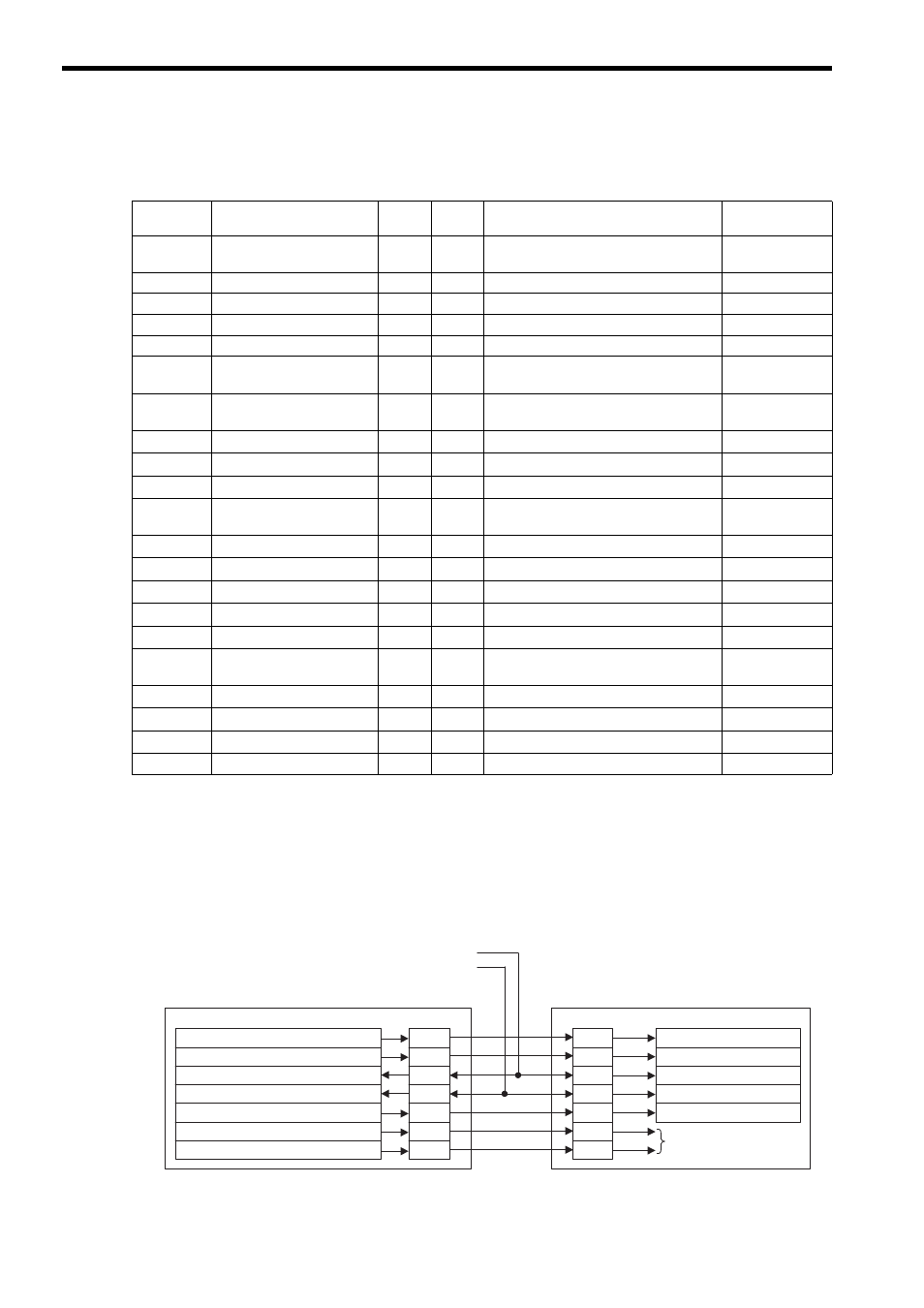
The I/O signals related to the SVA-01 are shown in the following connection diagram.
Parameter
No.
Name
Default
Value
Set
Value
Setting Contents
Remarks
Pn000.1
Control method selection
0
9
Torque control (analog reference)
↔
Speed control (analog reference)
Pn002.0
Speed control option
0
1
Use T-REF as external torque limit input.
*1
Pn002.1
Torque control option
0
1
Use V-REF as external speed limit input.
Pn003.0
Analog monitor 1
2
2
Torque reference monitor
Pn003.1
Analog monitor 2
0
0
Motor speed
Pn50A.0
Input signal allocation
mode
0
1
Enables free allocation of input signals.
Pn50A.1
/S-ON signal mapping
0
0
Input signal from CN1-40 input terminal.
Used by SVA-01
system.
Pn50A.2
/P-CON signal mapping
1
8
Signal always disabled.
*2
Pn50A.3
P-OT signal mapping
2
2
Input signal from CN1-42 input terminal.
*2
Pn50B.0
N-OT signal mapping
3
3
Input signal from CN1-43 input terminal.
*2
Pn50B.1
/ALM-RST signal mapping
4
4
Input signal from CN1-44 input terminal.
Used by SVA-01
system.
Pn50B.2
/P-CL signal mapping
5
8
Signal always disabled.
*2
Pn50B.3
/N-CL signal mapping
6
8
Signal always disabled.
*2
Pn50C.0
/SPD-D signal mapping
8
8
Signal always disabled.
Cannot be used.
Pn50C.1
/SPD-A signal mapping
8
8
Signal always disabled.
Cannot be used.
Pn50C.2
/SPD-B signal mapping
8
8
Signal always disabled.
Cannot be used.
Pn50C.3
/C-SEL signal mapping
8
1
Input signal from CN1-41 input terminal.
Used by SVA-01
system.
Pn50D.0
/ZCLAMP signal mapping
8
8
Signal always disabled.
Cannot be used
Pn50D.1
/INHIBIT signal mapping
8
8
Signal always disabled.
Cannot be used
Pn50D.2
/G-SEL signal mapping
8
8
Signal always disabled.
*2
Pn515.0
/G-SEL2 signal mapping
8
8
Signal always disabled
*2, *3
CN1/CN2
General-purpose input N-OT
General-purpose input P-OT
SGDH/SGDS/SGDV SERVOPACK
CN1
SVA-01 Module
Setting/Monitoring Parameters
Selection Functions
/S-ON
OW
00, bit 0: Servo ON
31
40
Internal variable: Switches control mode
/P-CON
12
41
IW
58, bit 4: General-purpose DI_4
33
/N-OT (Can be set by user.)
43
OW
00, bit 15: Alarm clear
/ALM RST
30
44
IW
58, bit 3: General-purpose DI_3
15
/P-OT (Can be set by user.)
42
OW
5D, bit 3: General-purpose DO_3
14
46
OW
5D, bit 4: General-purpose DO_4
13
45
Set by user.