3 switch rear panel – PLANET WGS3-24240 User Manual
Page 28
User’s Manual of WGS3-24000 / WGS3-24240
28
LED
Color
Function
LNK/ACT
Green
Lights to indicate the link through that port is successfully established.
Blink: indicate that the switch is actively sending or receiving data over that port.
■
10/100/1000Base-T interfaces (Port-11, Port-12, Port-23 and Port-24)
LED
Color
Function
LNK/ACT
Green
Lights to indicate the link through that port is successfully established.
Blink: indicate that the switch is actively sending or receiving data over that port.
1000
Green
Lights to indicate the port is running in 1000Mbps speed.
Off: indicate that the port is operating at 10Mbps or 100Mbps.
FDX
Orange
Lights to indicate the link through that port is established at Full Duplex mode
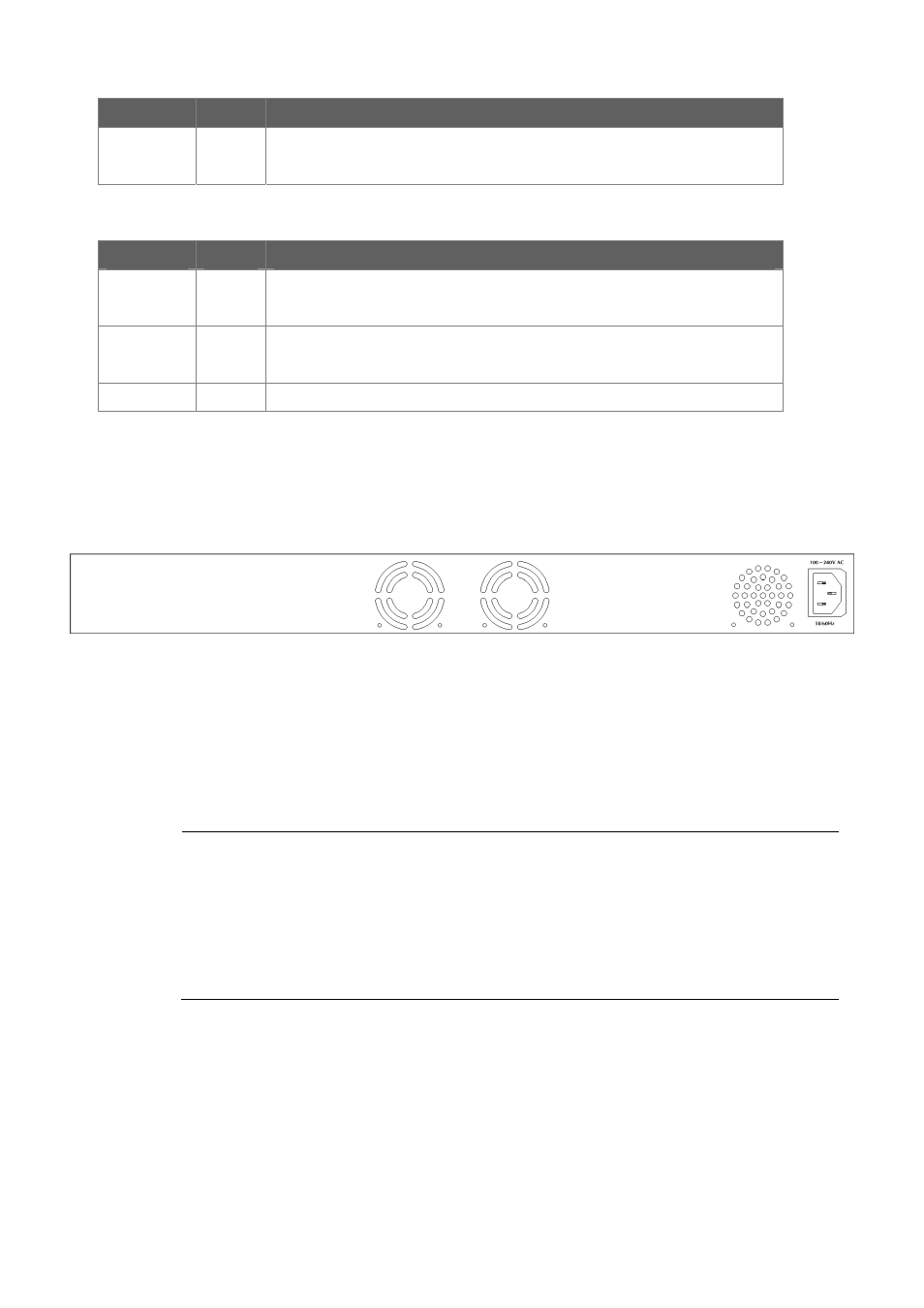
2.1.3 Switch Rear Panel
The rear panel of the WGS3-Layer 3 Switch indicates an AC inlet power socket, which accept input power from 100 to 240V AC,
50-60Hz. Figure 2-2 shows the rear panel of the switch
Figure 2-4 Rear panel of WGS3-24000 and WGS3-24240.
■
Power Receptacle
For compatibility with electric service in most areas of the world, the WGS3-Layer 3 Switch’s power supply automatically
adjusts to line power in the range 100-240VAC and 50/60 Hz.
Plug the female end of the power cord firmly into the receptalbe on the rear panel of the Switch. Plug the other end of the
power cord into an electric service outlet then the power will be ready.
Power Notice:
1. The device is a power-required device, it means, it will not work till it is powered. If your networks
should active all the time, please consider using UPS (Uninterrupted Power Supply) for your device. It
will prevent you from network data loss or network downtime.
2. In some area, installing a surge suppression device may also help to protect your WGS3 Layer 3
Switch from being damaged by unregulated surge or current to the Switch or the power adapter.