3) i/o reference number setting, 4) i/o data format – Yaskawa 120 Series I/O Modules User Manual
Page 112
3 Digital I/O Specifications
3.4.1 16-point Input Modules
3-82
3) I/O Reference Number Setting
(a) The leading I/O reference number used by the Input Module is set.
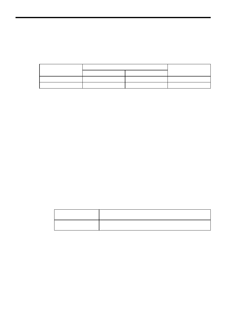
(b) Any one of the I/O reference numbers and points listed in the following table
can be set.
(c) When an input relay is set, the leading I/O reference number must satisfy the
following equation:
Leading reference number of I/O relay = 100001 + 16 n
where n = 0 to 63 for the CPU20 and
n = 0 to 255 for the CPU30
For example, 100001 can be set as the leading reference number, but
100002 cannot.
4) I/O Data Format
The following items can be set to define the I/O data format. There is, however, gen-
erally no need to change these settings because the default settings can be used
for most normal applications.
a) Bit Order
I/O can be processed by handling data either in ascending or descending order of
the bits. This is explained next for allocation of both input relays and input registers.
(1) When 16-point input relays are allocated from 100001, the bit order can be set
to either “MSB” or “LSB,” as described in the following table and shown in the
illustration below it.
Refer to Fig. 3.1 Allocation of Input Relays for details.
Type of Input
References for I/O Allocation
Points/Registers
CPU10, CPU20, CPU21
CPU30, CPU35
Input Relays
100001 to 101024
100001 to 104096
16 points
Input Registers
300001 to 300512
300001 to 300512
One register
Input Relay MSB Setting
The leading input reference number (100001) is allocated to the
smallest input number (input 1) on the Input Module.
Input Relay LSB Setting
The leading input reference number (100001) is allocated to the larg-
est input number (input 16) on the Input Module.