Yaskawa 120 Series I/O Modules User Manual
Page 152
4.1 Analog Input Specifications
4-5
4
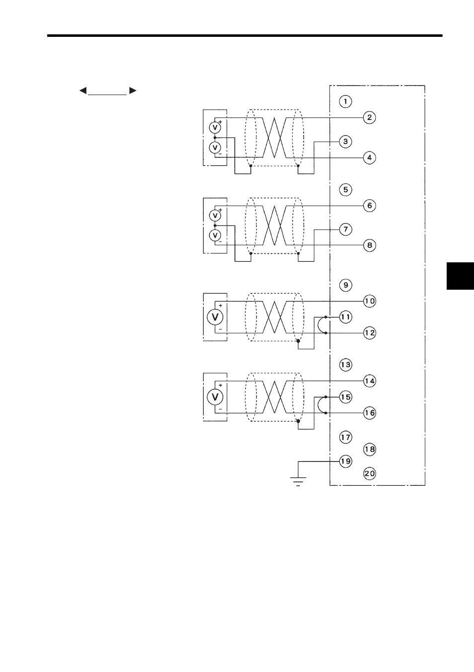
4) The following diagram shows an example of terminal connections.
Note: (1) Isolation between Input Channels
There is no insolation provided between the input circuit channels. If isolation
between channels is required, use a commercial isolation amplifier for each
channel.
(2) Recommended Cables
Use shielded twisted-pair wires 1.3 mm
2
(AWG16) to 0.5 mm
2
(AWG20) to con-
nect to the terminal block.
EXAMPLE
For Differential Signal Source
External device
Shielded twisted-pair wire
Not connected
Shield 1
External device
Shielded twisted-pair wire
Not connected
Shield 2
For Single-ended Signal Source
External device
Shielded twisted-pair wire
Not connected
Shield 3
External device
Shielded twisted-pair wire
Not connected
Shield 4
Not connected
Not connected
Not connected
-10 to 10 V
-10 to 10 V
-10 to 10 V
-10 to 10 V
FG
CH1 V+
CH1 V-
CH4 V-
CH4 V+
CH3 V-
CH3 V+
CH2 V+
CH2 V-
Grounding resistance
100
Ω max.