Example – Yaskawa 120 Series I/O Modules User Manual
Page 46
3 Digital I/O Specifications
3.1.4 12/24-VDC 32-point Input Module
3-16
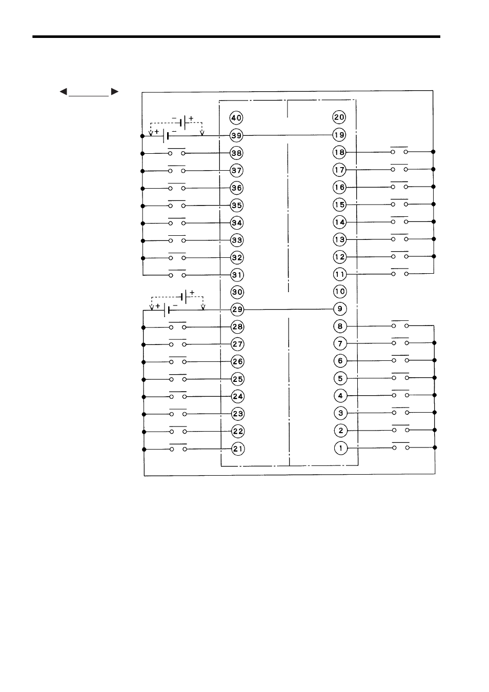
3) The following diagram shows an example or terminal connections.
Note: (1) Pins 9 and 29, pins 19 and 39 are internally connected.
Connect these pins externally as well. Not connecting
them can cause malfunction.
(2) Connectors for External Connections
On the Module: 10240-52A2JL (manufactured by 3M)
(3) Recommended wires
Use wires of 0.08mm
2
(AWG28) to connect to each pin of
the connector.
(4) The polarity of the external power supply for signals can be
connected with either plus or minus.
(5) Pins 10, 20, 30, and 40 are not connected.
(6) External Connection Cable
Use a 32-point I/O Module Cable to connect to field
devices. Refer to 3.3 I/O Module Cables for details.
Input 32
Common 2
Not
connected
Not
connected
Input 30
Input 28
Input 26
Input 24
Input 22
Input 20
Input 18
Not
connected
Not
connected
Common 1
Input 31
Input 29
Input 27
Input 25
Input 23
Input 21
Input 19
Input 17
Input 16
Input 14
Input 12
Input 10
Input 8
Input 6
Input 4
Input 2
Input 15
Input 13
Input 11
Input 9
Input 7
Input 5
Input 3
Input 1
12/24 VDC
12/24 VDC
Pin No.
Pin No.
EXAMPLE