3 external wiring, 1 external wiring for digital i/o modules, 2) laying digital i/o signal cables – Yaskawa 120 Series I/O Modules User Manual
Page 258
6.3 External Wiring
6-31
6
6.3
External Wiring
6.3.1 External Wiring for Digital I/O Modules - - - - - - - - - - - - - - - - - - - - - - 6-31
6.3.1
External Wiring for Digital I/O Modules
1) Selection and Separation of Digital I/O Signal Cables
The digital I/O signal cable used for external wiring for Digital I/O Modules must be
selected according to the operating environment, including the mechanical strength,
effects of electric noise, voltage used, etc. Use the following table to select and sep-
arate appropriate I/O signal cables.
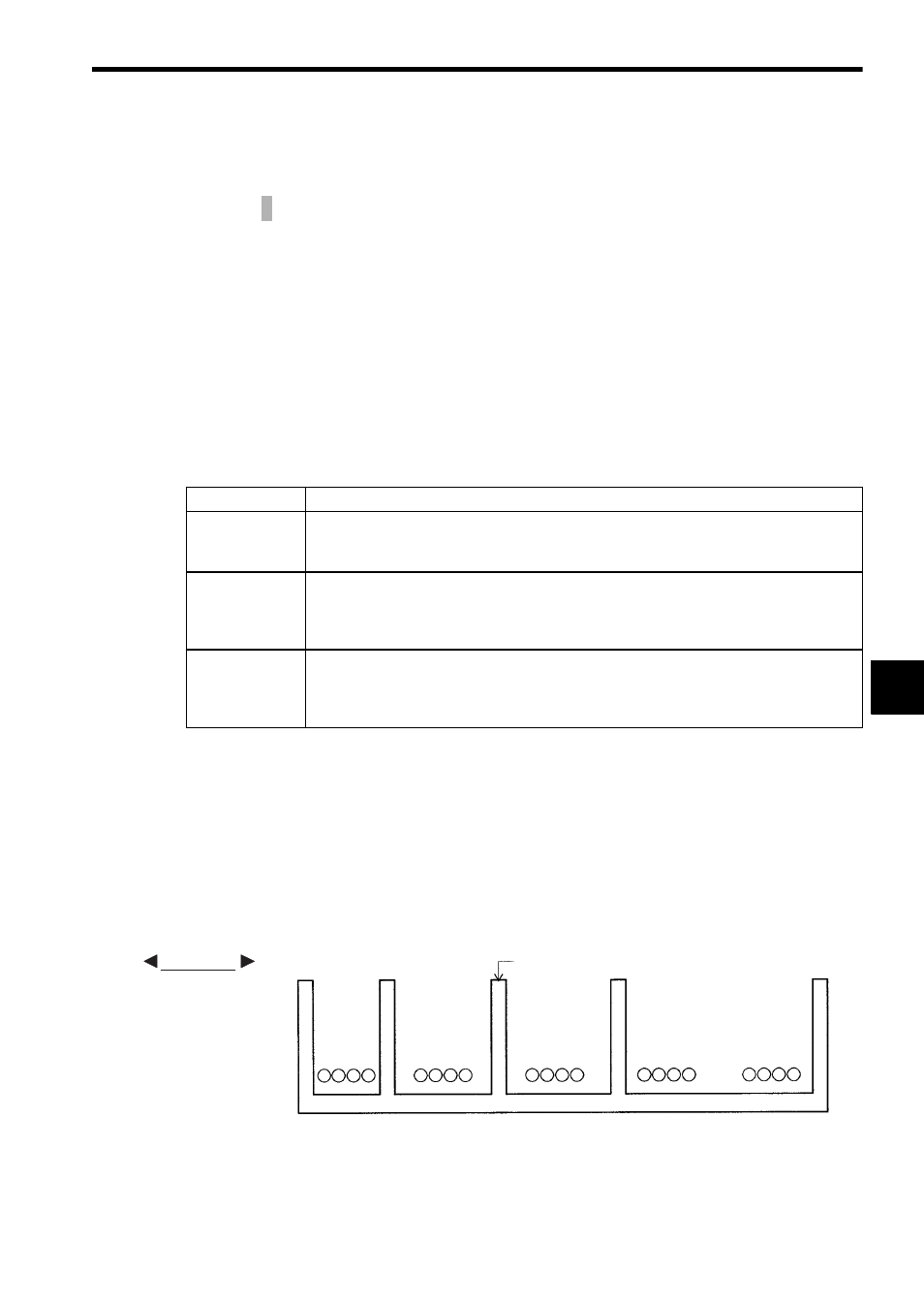
2) Laying Digital I/O Signal Cables
I/O signal cables connected to Digital I/O Modules must be separated form general
control circuit cables and power circuit cables as much as possible.
Leave 10 cm or more between digital I/O signal cables and a general control circuit
cables, and 20 cm or more between digital I/O signal cables and power circuit
cables. If separation is not possible, then use fully shielded cables, or as shown in
the following figure, take measures such as separating them by way of iron plate
separators.
This section describes the basic external wiring procedure for Digital I/O Modules.
Table 6.14 Wiring Procedures for Digital I/O Signal Cables
Wiring Length
Procedures
30 m or less
a) A DC output signal line, a DC input signal line, an AC output signal line, and an AC
input signal line may be housed in the same cable.
b) DC I/O signal lines and AC I/O signal lines must be housed in separate cables.
30 to 300 m
a) Each DC output signal line, DC input signal line, AC output signal line, and AC input
signal line must be housed in a separate cable.
b) If the induction voltage is large, attach either dummy resistance, or use a separate
fully shielded cable and ground the shield on the GL120 and GL130 end.
300 m or longer
a) Considering the inrush current to Output Module, the length of cable must be 300 m
or less.
b) When the wiring length is more than 300 m, install a junction relay in between so that
the length between the junction relay and the control panel is not more than 30 m.
EXAMPLE
Steel-plate separator
Power
circuit
cables
General control
circuit cables
Digital I/O
signal cables
Analog I/O
signal cables
Pulse input
signal
cables