Caution – Yaskawa 120 Series I/O Modules User Manual
Page 81
3.2 Digital Output Module Specifications
3-51
3
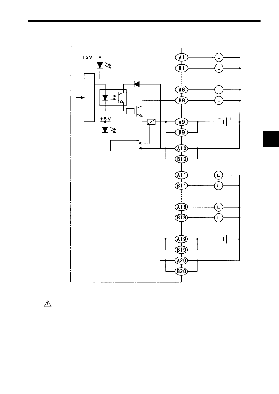
If using a 12/24-VDC 64-point Output Module, connect a fuse, which complies with
the load specifications, in series with the load.
A protective fuse built into the following 12/24-VDC 64-point Output Modules
does not protect the output element. If a fuse is not connected, a fire or dam-
age to the devices or output circuits may occur if the load is short-circuited or
the circuit overloaded.
Loads
Output 33
Output 34
Output 47
Output 48
- Common 3
Output 49
Output 50
12/24 VDC
Loads
Output 63
Output 64
- Common 4
+ Common 3
+ Common 4
12/24 VDC
(Continued from previous page)
Output signal
indicator
From CPU
Photocoupler
Fuse
CN2 connector
pin numbers
Blown fuse/power
disconnection indi-
cator
Blown-fuse
detection circuit
Internal circuits
CAUTION