Yaskawa 120 Series I/O Modules User Manual
Page 130
3 Digital I/O Specifications
3.4.6 32-point Output Modules
3-100
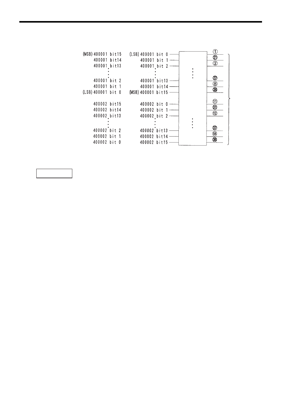
Fig. 3.12 Allocation of Output Registers
When allocating output registers, the MEMOSOFT is set by default to “LSB.”
When output register allocation is set to “LSB,” bit 15 (MSB) of the output register is
allocated to the smallest output number (output 1) on the Output Module.
b) Output Data Type
If an output register is set as the I/O reference number, data output can be set to
binary (BIN) or BCD. The MEMOSOFT is set by default to “BIN.”
c) Service Scan: Normal/High-speed
Two types of service scans are available: normal and high-speed. A service scan
is recommended when using the high-speed segment function. The I/O module is
activated before the ladder decoding of the high-speed segments. The I/Os that are
processed in synchronization with the high-speed scan are called High-speed Seg-
ment I/Os. The MEMOSOFT is set by default to “NORMAL.”
d) Timeout Output
The data that is output when the CPU Module changes from a running status to a
stopped status can be specified. Either of the following settings is possible.
(1) Final Data: The data that existed just prior to stopping.
(2) Set Data: Preset data.
The MEMOSOFT is set by default to SET DATA.
e) Timeout Output Data
The data that is output when the CPU Module stops (when set data is specified for
the timeout output) can be set. The data set here is an image of the PC reference
data. The data set here is converted and output in the order bits are set. The
MEMOSOFT is set by default to all zeros.
Terminal number
Output signals
LSB Setting
MSB Setting
Output 1
Output 2
Output 3
Output 14
Output 15
Output 16
Output 17
Output 18
Output 19
Output 30
Output 31
Output 32
IMPORTANT