Yaskawa 120 Series I/O Modules User Manual
Page 52
3 Digital I/O Specifications
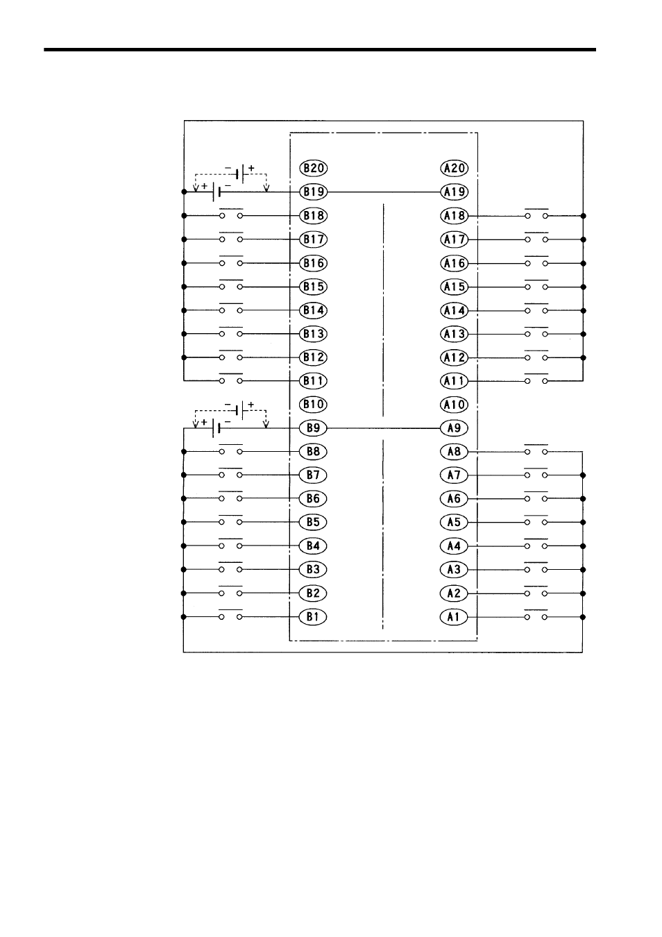
3.1.5 12/24-VDC 64-point Input Module
3-22
Note: (1) CN2 pins A9 and B9 and pins A19 and B19 are internally connected. Connect
these pins externally as well. Not connecting them can cause malfunction.
(2) Pins A10, A20, B10, and B20 are not connected.
(3) The polarity of the external power supply for signals can be either positive or
negative.
(4) Connector for External Connections (included)
Connector: FCN-361J040-AU (soldered) (manufactured by Fujitsu Ltd.)
Cover: FCN-360C040-B (manufactured by Fujitsu Ltd.)
(5) Recommended Wires
Use wires of 0.26 mm
2
(AWG23) to connect to each connector pin.
(6) External Connection Cable
Two pairs of connectors to connect the external input signal and a 64-point I/O
Module Cable to connect to field devices are provided. For details, refer to 3.3
I/O Module Cables.
12/24 VDC
CN2 connector
pin numbers
Input 64
Common 4
Input 62
Input 58
Input 56
Input 54
Input 52
Input 50
Input 48
Input 60
Common 3
Input 46
Input 44
Input 42
Input 40
Input 38
Input 36
Input 34
(Continued from previous page)
Not
connected
Input 63
Common 4
Input 61
Input 57
Input 55
Input 53
Input 51
Input 49
Input 47
Input 59
Common 3
Input 45
Input 43
Input 41
Input 39
Input 37
Input 35
Input 33
CN2 connector
pin numbers
Not
connected
Not
connected
Not
connected
12/24 VDC