Yaskawa 120 Series I/O Modules User Manual
Page 271
6 Installation and Wiring
6.4.3 DC Input Modules
6-44
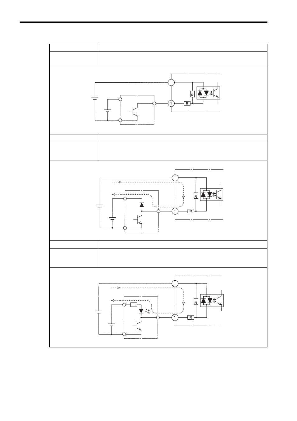
Input Device
Open collector output (V1
> V2)
Connection
Can be connected.
The voltage resistance of the output transistor in the input
device must be 40 V or more.
Input Device
Output with a diode (V1
> V2)
Connection
Cannot be connected. When the input device is OFF, current indicated by the dot-
ted line in the figure on the left may flow, and the input may
not turn OFF.
Input Device
Output with a resistor and LED (V1
> V2)
Connection
Cannot be connected. When the input device is OFF, current indicated by the dot-
ted line in the figure on the left may flow and apply reverse
voltage to the LED, possibly damaging the LED.
V1: Input signal power supply
V2: Input device power supply
DC Input Module
+Common 1
Photocoupler
Input
Input device
V1
24 VDC
V2
12 VDC
9
V1: Input signal power supply
V2: Input device power supply
DC Input Module
+Common 1
Photocoupler
Input
Input device
V1
24 VDC
V2
12 VDC
9
V1: Input signal power supply
V2: Input device power supply
DC Input Module
+Common 1
Photocoupler
Input
Input device
V1
24 VDC
V2
12 VDC
9