4) grounding the control panel, 5) grounding method – Yaskawa 120 Series I/O Modules User Manual
Page 257
6 Installation and Wiring
6.2.5 Grounding
6-30
4) Grounding the Control Panel
a) Connect the ground terminal of the control panel and the ground pole with a cable
(outside-panel ground cable) of 8 mm
2
(AWG8) or larger. Make sure that the length
of this ground cable is as short as possible.
b) Use a ground pole with a resistance of 100
Ω max. Do not use together with ground
cables or ground poles of high-voltage electrical devices.
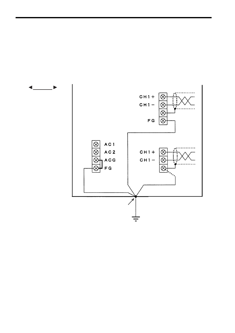
The following figure shows an example of the ground cable connection.
Fig. 6.7 Ground Cable Connection Example
5) Grounding Method
a) Dedicated Ground
As a rule, the Modules forming the GL120 or GL130 should be grounded to an inde-
pendent ground pole at a ground resistance of 100
Ω
max.
b) Common Ground Pole
The Modules forming the GL120 or GL130 and devices related to general control
circuits can share a common ground pole. Do not, however, share the same ground
pole between GL120 or GL130 Modules and power devices.
c) Common Ground Line
The Modules forming the GL120 or GL130 and devices related to general control
circuits cannot share a common outside-panel ground cable.
EXAMPLE
Analog Input Module
field wiring terminal
Shield 1
In-panel ground cable
Analog Output Module
field wiring terminal
Not connected
(junction terminals)
In-panel ground cable
(Connect when necessary)
Outside-panel ground cable (8 mm
2
or lager)
Ground pole (with a resistance of 100
Ω max.)
Ground terminal (E)
Control panel
In-panel ground cable
(1.5 mm
2
to 2.5 mm
2
)
Power Supply Module
field wiring terminal