2) module type setting, 3) i/o reference number setting – Yaskawa 120 Series I/O Modules User Manual
Page 118
3 Digital I/O Specifications
3.4.3 64-point Input Modules
3-88
Refer to the following manuals for specific setting procedures.
• MEOCON GL120, GL130 MEMOSOFT for P120 Programming Panel User’s
Manual (Manual No. SIEZ-C825-60.7), Chapter 7 Setting System Configuration.
• MEMOCON GL120, GL130 MEMOSOFT for DOS User’s Manual (Manual No.
SIEZ-C825-60.10), Chapter 7 Setting System Configuration.
• MEMOCON GL120, GL130 MEMOSOFT for Windows User’s Manual (Manual
No. SIEZ-C825-60.25), Chapter 6 Setting the Module Configuration.
2) Module Type Setting
The type of Input Module mounted in the slot is set as the Module type. Only the last
11 alphanumeric characters of the model number are necessary. For example
120DDI36400 is the Module type for the JAMSC-120DDI36400.
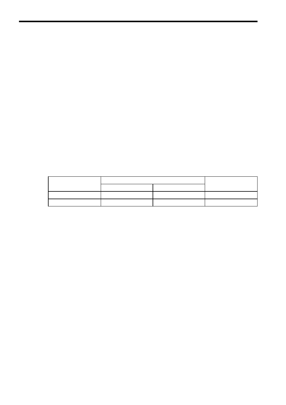
3) I/O Reference Number Setting
(a) The leading I/O reference number used by the Input Module is set.
(b) Any one of the I/O reference numbers and points listed in the following table
can be set.
(c) When an input relay is set, the leading I/O reference number must satisfy the
following equation:
Leading reference number of I/O relay = 100001 + 16 n
where n = 0 to 63 for the CPU20 and
n = 0 to 255 for the CPU30
For example, 100001 can be set as the leading reference number, but
100002 cannot.
Type of Input
References for I/O Allocation
Points/Registers
CPU10, CPU20, CPU21
CPU30, CPU35
Input Relays
100001 to 101024
100001 to 104096
64 points
Input Registers
300001 to 300512
300001 to 300512
4 registers