Caution – Yaskawa 120 Series I/O Modules User Manual
Page 72
3 Digital I/O Specifications
3.2.5 12/24-VDC 16-point Output Module (Sourcing)
3-42
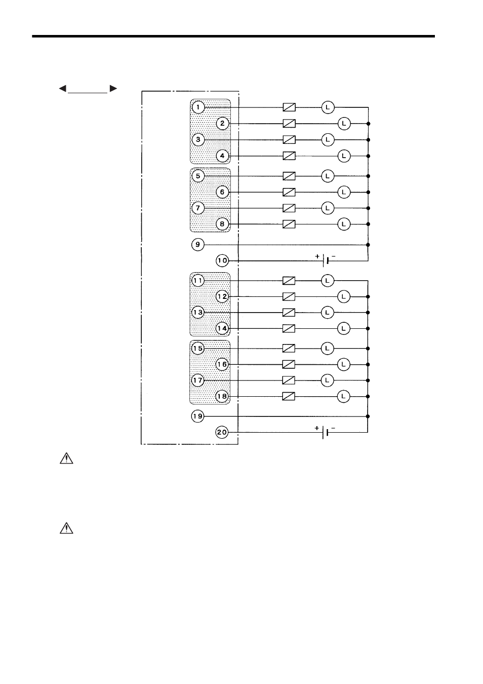
3) The following diagram shows an example of terminal connections.
Although a 0.5 A load can be connected to each output point of the 12/24-VDC 16-
point Output Module (sourcing), the total load must be 1.0 A or less for each of the
four output points shown in the shaded area. Keep the load distribution within the 1.0
A limit.
It this limit is exceeded, damage may occur to the output circuit.
If using a 12/24-VDC 16-point Output Module (sourcing), connect a fuse, which
complies with the load specifications, in series with the load.
A protective fuse built into the following 12/24-VDC 16-point Output Modules
does not protect the output element. If a fuse is not connected, a fire or dam-
age to the devices or output circuits may occur if the load is short-circuited or
the circuit overloaded.
Note: (1) Crimp Terminals
Use M3 terminals for crimping to the terminal block.
(2) Recommended Wires
Use wires of 0.8mm
2
(AWG18) to 0.2mm
2
f(AWG24) to connect to the terminal
block.
Output 1
Output 2
Output 3
Output 4
Output 5
Output 6
Output 7
Output 8
- Common 1
+ Common 1
Output 9
Output 10
Output 11
Output 12
Output 13
Output 14
Output 15
Output 16
- Common 2
+ Common 2
Loads
Loads
Fuses
Fuses
12/24 VDC
12/24 VDC
EXAMPLE
CAUTION
CAUTION