Caution – Yaskawa 120 Series I/O Modules User Manual
Page 86
3 Digital I/O Specifications
3.2.8 Relay Contact 16-point Output Module
3-56
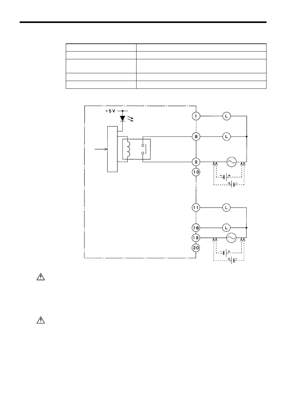
2) The following diagram shows the circuit configuration.
If using a single-phase 100/200-VAC power supply for driving loads of the Relay
Contact Output Module, connect a power supply of the same phase to the Common 1
and Common 2 of the Relay Contact Output Module.
If power supplies of different phases are connected, overheating or fire may
occur.
If using a Relay Contact Output Module, connect a fuse, which complies with the load
specifications, in series with the load.
A protective fuse does not built into the following Relay Contact Output Mod-
ules. If a fuse is not connected, fire or damage to the devices or output circuits
may occur if the load is short-circuited or the circuit overloaded.
Maximum Heating Value
3.1 W
Hot Swapping
(Removal/insertion under power)
Permitted
Approximate Mass
300 g
External Dimensions
40.3
×130×103.9 mm (W×H×D)
Item
Specifications
Output 1
Output 8
Common 1
Output 9
Output 16
Common 2
12/24 VDC
12/24 VDC
Output signal
indicator
From CPU
Relay
Loads
Loads
100/200 VAC
100/200 VAC
Internal circuits
CAUTION
CAUTION