Caution – Yaskawa 120 Series I/O Modules User Manual
Page 59
3.2 Digital Output Module Specifications
3-29
3
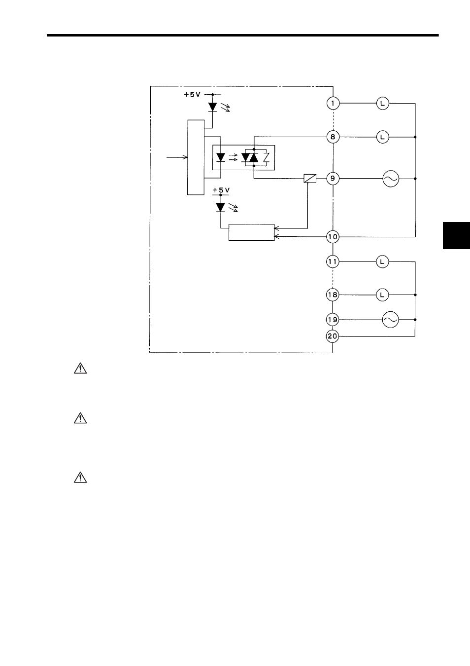
2) The following diagram shows the circuit configuration.
Do not replace the built-in fuse of the 100/200-VAC 16-point Output Modules.
If the built-in fuses are replaced by anyone other than a Yaskawa-approved
technician, failure or malfunction may occur in the Modules.
Connect power supplies of the same phase to the Common 1 and Common 2 of the
AC I/O Module.
If power supplies of different phases are connected, overheating or fire may
occur.
If using a 100/200-VAC 16-point Output Module, connect a fuse, which complies with
the load specifications, in series with the load.
A protective fuse built into the following 100/200-VAC 16-point Output Modules
does not protect the output element. If a fuse is not connected, a fire or dam-
age to the devices or output circuits may occur if the load is short-circuited or
the circuit overloaded.
Output 1
Output 8
Common 1-1
Output 9
Output 16
Common 2-1
100/200 VAC
100/200 VAC
Output signal
indicator
From CPU
Phototriac
Common 1-2
Common 2-2
Loads
Loads
Fuse
Blown fuse
Power not
connected indicator
Blown fuse
detection circuit
Internal circuits
CAUTION
CAUTION
CAUTION