Yaskawa 120 Series I/O Modules User Manual
Page 251
6 Installation and Wiring
6.2.3 Wiring DC I/O Modules
6-24
c) Use the following electric wires and connectors to assemble I/O signal cables to con-
nect to these Digital I/O Modules:
• Cable size: 0.26mm
2
(AWG23)
• Module side connector (provided as accessory):
Connector: FCN-361J040-AU (soldered) (manufactured by Fujitsu Ltd.)
Cover: FCN-360C040-B (manufactured by Fujitsu Ltd.)
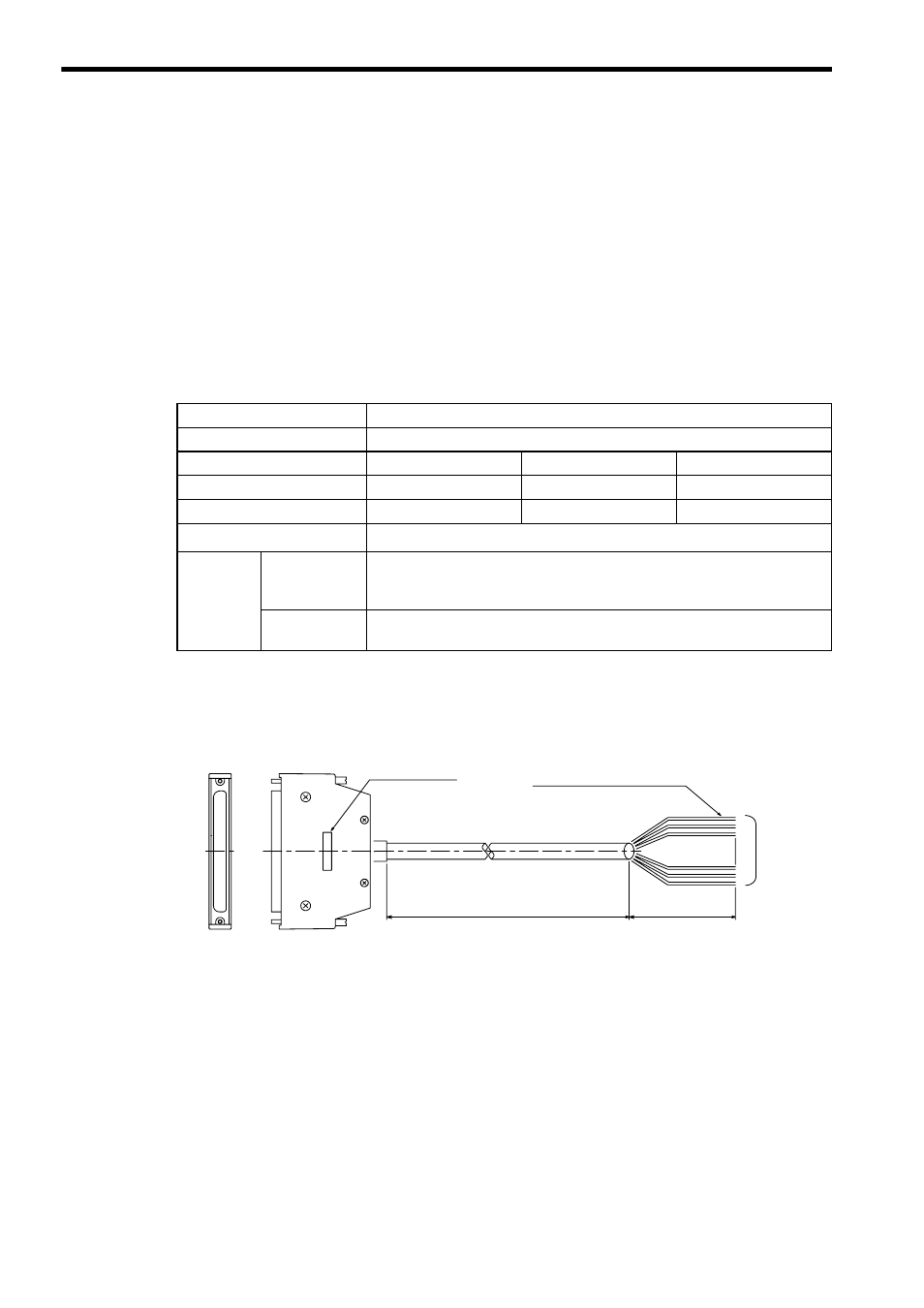
d) If a W5410 64-point I/O Module Cable is used, select the appropriate cable from the
following table.
As shown in the following figure, the external-device end of the W5410 cable has
loose wires. The size of each wire is 0.20 mm
2
.
e) If using an insulation transformer for the primary side of the DC-voltage stabilizing
power supply, make sure to separate the primary and the secondary coils. If using a
noise filter, also be sure to separate the primary and the secondary coils.
Table 6.12 W5410 64-point I/O Module Cables
Item
Specifications
Name
W5410 Cable
Model Name
W5410-05
W5410-10
W5410-30
Model No.
JEPMC-W5410-05
JEPMC-W5410-10
JEPMC-W5410-30
Length (L)
0.5m
1.0m
3.0m
Cable Specifications
Shielded cable of 40 conductors, AWG24 (0.20 mm
2
)
Terminals
Module Side
Connector: FCN-363J-040 (manufactured by Fujitsu Ltd.)
FCN-360C040-B (manufactured by Fujitsu Ltd.)
FCN-363J-AU/R (manufactured by Fujitsu Ltd.)
External
device Side
Loose wires; Cable length: 100 mm, pin number labeled on each wire
A pin number label is on
each loose wire.
L
100 mm
Model name
Connector (Module side)
Shielded cable
Loose wires (external-device side)
40-core
loose wires