4) i/o data format – Yaskawa 120 Series I/O Modules User Manual
Page 123
3.4 I/O Allocation
3-93
3
(c) When an output coil is set, the leading I/O reference number must satisfy the
following equation:
Leading reference number of I/O coil = 000001 + 8 n
where n = 0 to 127 for the CPU20 and
n = 0 to 511 for the CPU30
For example, 000001 can be set as the leading reference number, but
000002 cannot.
Note: Output registers cannot be allocated for the 8-point Output
Modules.
4) I/O Data Format
The following items can be set to define the I/O data format. There is, however, gen-
erally no need to change these settings because the default settings can be used
for most normal applications.
a) Bit Order
I/O can be processed by handling data either in ascending or descending order of
the bits. This is explained next for allocating from the reference number 000001 and
also from the reference number 000009.
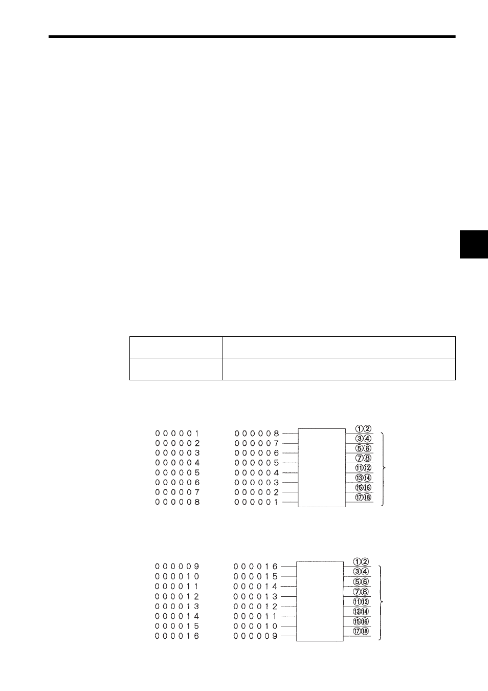
The bit order can be set to either “MSB” or “LSB,” as described in the following table
and shown in the illustration below it.
Refer to Fig. 3.7 and Fig. 3.8 for details.
(1) When allocating the output coils to eight output points from 000001
Fig. 3.7 Allocation Output Coils from 000001
(2) When allocating the output coils to eight output points from 000009
Fig. 3.8 Allocation Output Coils from 000009
Output Coil MSB Setting
The leading output reference number (000001 or 000009) is allocated
to the smallest output number (output 1) on the Output Module.
Output Coil LSB Setting
The leading output reference number (000001 or 000009) is allocated
to the largest output number (output 8) on the Output Module.
Terminal number
Output signals
MSB Setting
LSB Setting
Output 1
Output 2
Output 3
Output 4
Output 5
Output 6
Output 7
Output 8
Terminal number
Output signals
MSB Setting
LSB Setting
Output 1
Output 2
Output 3
Output 4
Output 5
Output 6
Output 7
Output 8