Yaskawa 120 Series I/O Modules User Manual
Page 181
4 Analog I/O Specifications
4.2.3 Analog Output Modules (4 to 20-mA, 2 channels)
4-34
5) I/O Allocation
I/O allocation is necessary when using the Analog Output Module (4 to 20-mA, 2
channels). For further details on I/O allocation, refer to 4.3 I/O Allocation.
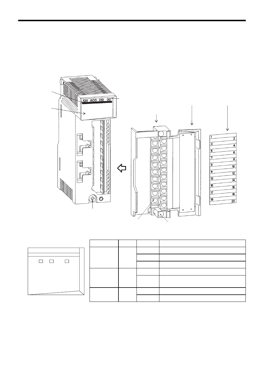
6) External Appearance
LED
Color
State
Indication when ON
RDY
Green
Lit
Module is normal.
Flashing
Initial check error has occurred.
Not lit
WDT timeout error has occurred.
ACT
Green
Lit
Module is processing I/O.
Not lit
CPU Module is in the STOP state or I/O pro-
cessing error has occurred.
ERR
Red
Flashing
Parameter checksum error has occurred.
Not lit
Module is normal.
Removable terminal block
for field connections
Hinged terminal cover
Signal label insert
Color code
(dark green)
LED area
Module mounting screw
(Use a M4 Phillips screwdriver.)
Module description (120ACO01000)
Field wiring terminal
(Use a M3 Phillips screwdriver.)
Terminal block mounting screw
(Use a M3 Phillips screwdriver.)
LED Area
120 ACO 010 00
ACT
ERR
RDY