Yaskawa 120 Series I/O Modules User Manual
Page 77
3.2 Digital Output Module Specifications
3-47
3
Note: (1) Pins 9 and 29, pins 19 and 39, pins 10 and 30, pins 20 and 40 are internally
connected. Connect these pins externally as well, otherwise, malfunction may
occur.
(2) Connector for External Connections
On the Module: 10240-52A2JL (made by 3M)
(3) Recommended Wires
Use wires of 0.08mm
2
(AWG28) to connect to each connector pin.
(4) External Connection Cable
Use a 32-point I/O Module Cable to connect to field devices. Refer to 3.3 I/O
Module Cables for details.
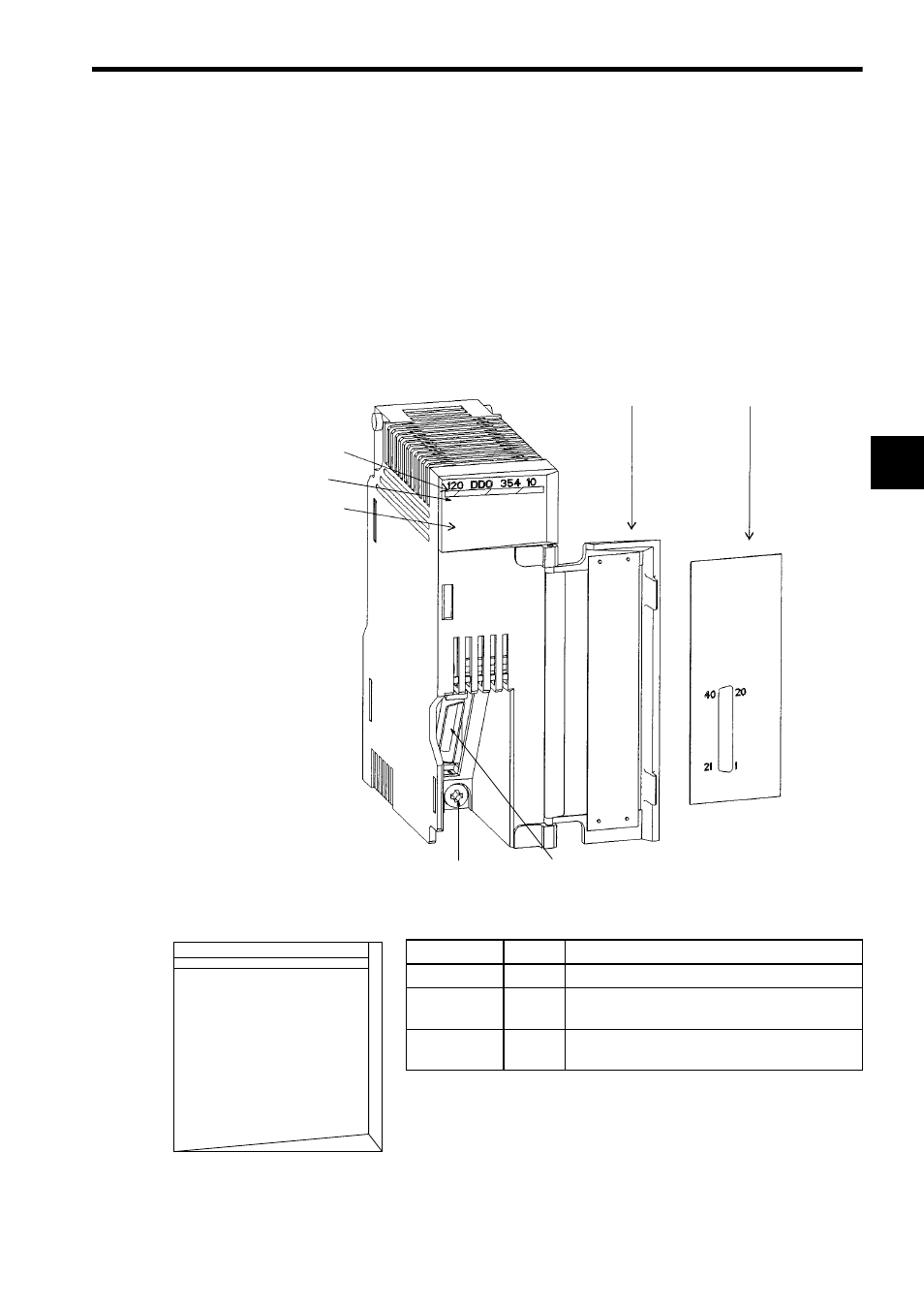
4) External Appearance
LED
Color
Indication when ON
ACTIVE
Green
Processing I/O.
F
Red
Fuse blown out, or external power supply not
connected.
1 to 32
Green
The corresponding LED is lit when the output
signal is ON.
Hinged terminal
cover
Signal label insert
Color code
(dark blue)
LED area
Module description
(120DDO35410)
Module mounting screw
(Use a M4 Phillips screwdriver.)
32-point I/O Module cable connector
LED Area
120 DDO 354 10
1
2
3
4
5
6
7
8
9
10
11
12
13
14
15
16
ACTIVE
17
18
19
20
21
22
23
24
25
26
27
28
29
30
31
32
F