Caution – Yaskawa 120 Series I/O Modules User Manual
Page 71
Advertising
3.2 Digital Output Module Specifications
3-41
3
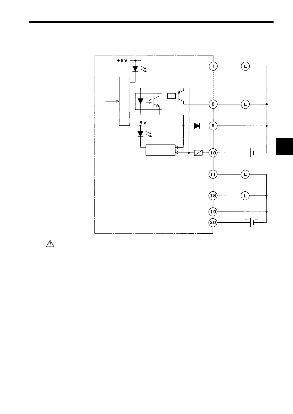
2) The following diagram shows the circuit configuration.
If using a 12/24-VDC 16-point Output Module (sourcing), connect a fuse, which
complies with the load specifications, in series with the load.
A protective fuse built into the following 12/24-VDC 16-point Output Modules
does not protect the output element. If a fuse is not connected, a fire or dam-
age to the devices or output circuits may occur if the load is short-circuited or
the circuit overloaded.
Output 1
Output 8
- Common 1
Output 9
Output 16
- Common 2
12/24 VDC
12/24 VDC
Output signal
indicator
From CPU
Photocoupler
+ Common 1
+ Common 2
Loads
Loads
Fuse
Blown-fuse
detection circuit
Blown fuse/
Power disconnected
indicator
Internal circuits
CAUTION
Advertising