Yaskawa 120 Series I/O Modules User Manual
Page 183

4 Analog I/O Specifications
4.3.1 Analog Input Modules
4-36
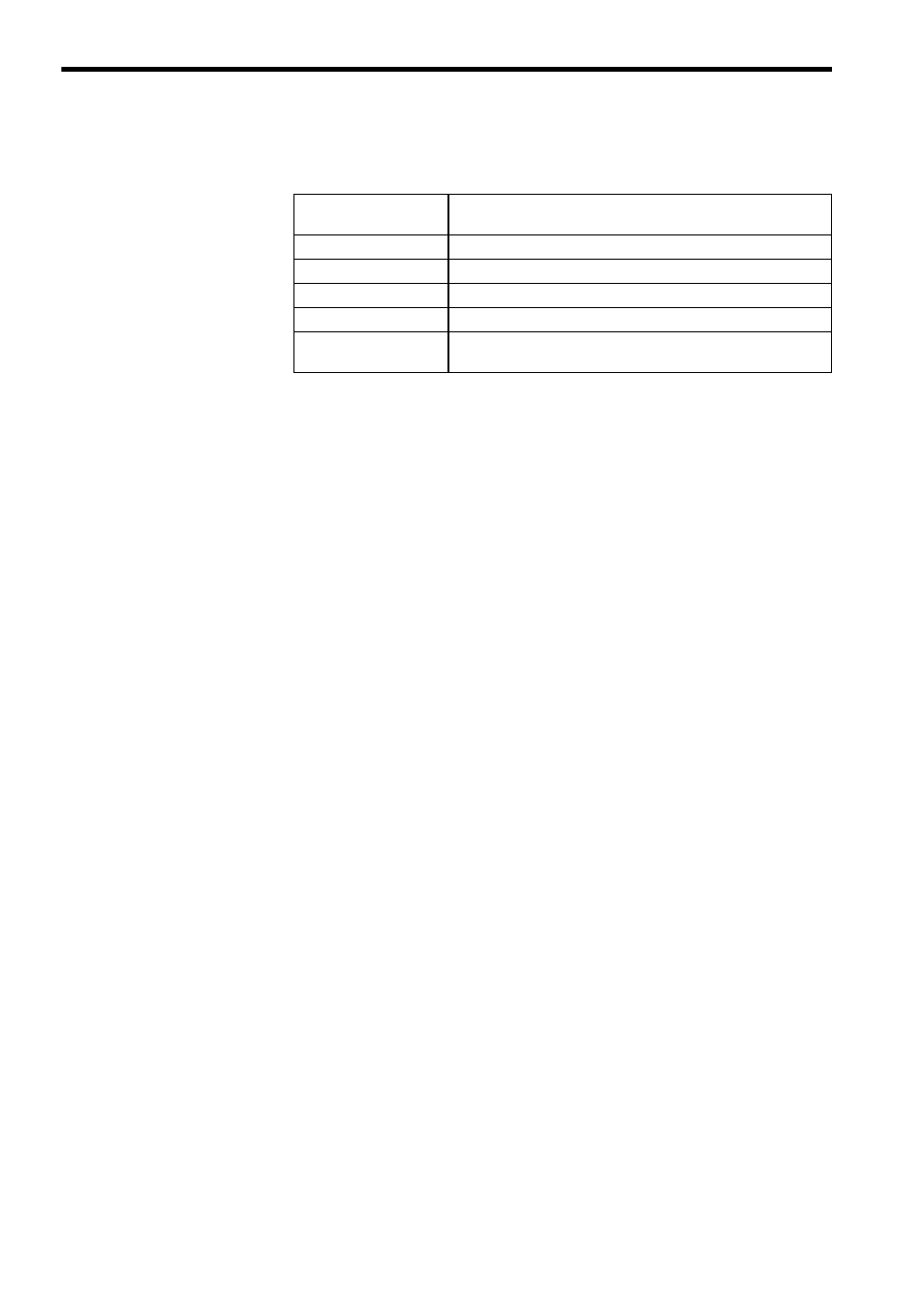
(3) The five input registers that are allocated are used as shown in the following
table. Here, n is between 0 and 507.
c) I/O Data Format
The following items can be set to define the I/O data format. There is, however, gen-
erally no need to change these settings, except for the mode setting, because the
default settings can be used for most normal applications.
(1) Mode Setting
(a) Analog Input Module (
±10V, 4 CH)
The data format can be set to either of the following formats.
•
±2000 mode: ±10 V / -2000 to +2000
• 0 to 4000 mode:
±10 V / 0 to 4000
The MEMOSOFT is set by default to the ±2000 mode.
(b) Analog Input Module (0-10V, 4 CH)
Only the 0 to 4000 mode can be used as the data format.
• 0 to 4000 mode: 0 to 10 V / 0 to +4000
The MEMOSOFT is set by default to the 0 to 4000 mode.
(c) Analog Input Module (4 to 20 mA, 4 CH)
Only the 0 to 4000 mode can be used as the data format.
• 0 to 4000 mode: 4 to 20 mA / 0 to +4000
The MEMOSOFT is set by default to the 0 to 4000 mode.
(2) Software Filter Setting
Software filters can be set. The following three settings are available.
• No filter: The input signal read by the Module is input by the CPU Module
at each scan.
• 3 input average: The average of three input signals read by the Module is
input by the CPU Module at each scan.
• 5 input average: The average of five input signals read by the Module is
input by the CPU Module at each scan.
The MEMOSOFT is set by default to use no filter.
Note: (1) The sampling interval for signals read by Input Modules is 4 ms.
(2) The data read by the CPU Module each scan is the most recent
signal or average read by the Input Module.
Input Register
Reference Number
Application
300001 + n
Analog input signal for channel 1
300002 + n
Analog input signal for channel 2
300003 + n
Analog input signal for channel 3
300004 + n
Analog input signal for channel 4
300005 + n
Analog input signal status for channels 1 to 4. Refer to d)
Input Signal Status for details.