2 panel wiring, 1 separation of power supply systems – Yaskawa 120 Series I/O Modules User Manual
Page 240
6.2 Panel Wiring
6-13
6
6.2
Panel Wiring
6.2.1 Separation of Power Supply Systems - - - - - - - - - - - - - - - - - - - - - - 6-13
6.2.2 Wiring AC I/O Modules - - - - - - - - - - - - - - - - - - - - - - - - - - - - - - - - - 6-14
6.2.3 Wiring DC I/O Modules - - - - - - - - - - - - - - - - - - - - - - - - - - - - - - - - - 6-17
6.2.4 Wiring Analog I/O Modules - - - - - - - - - - - - - - - - - - - - - - - - - - - - - - 6-25
6.2.5 Grounding - - - - - - - - - - - - - - - - - - - - - - - - - - - - - - - - - - - - - - - - - - 6-28
6.2.1
Separation of Power Supply Systems
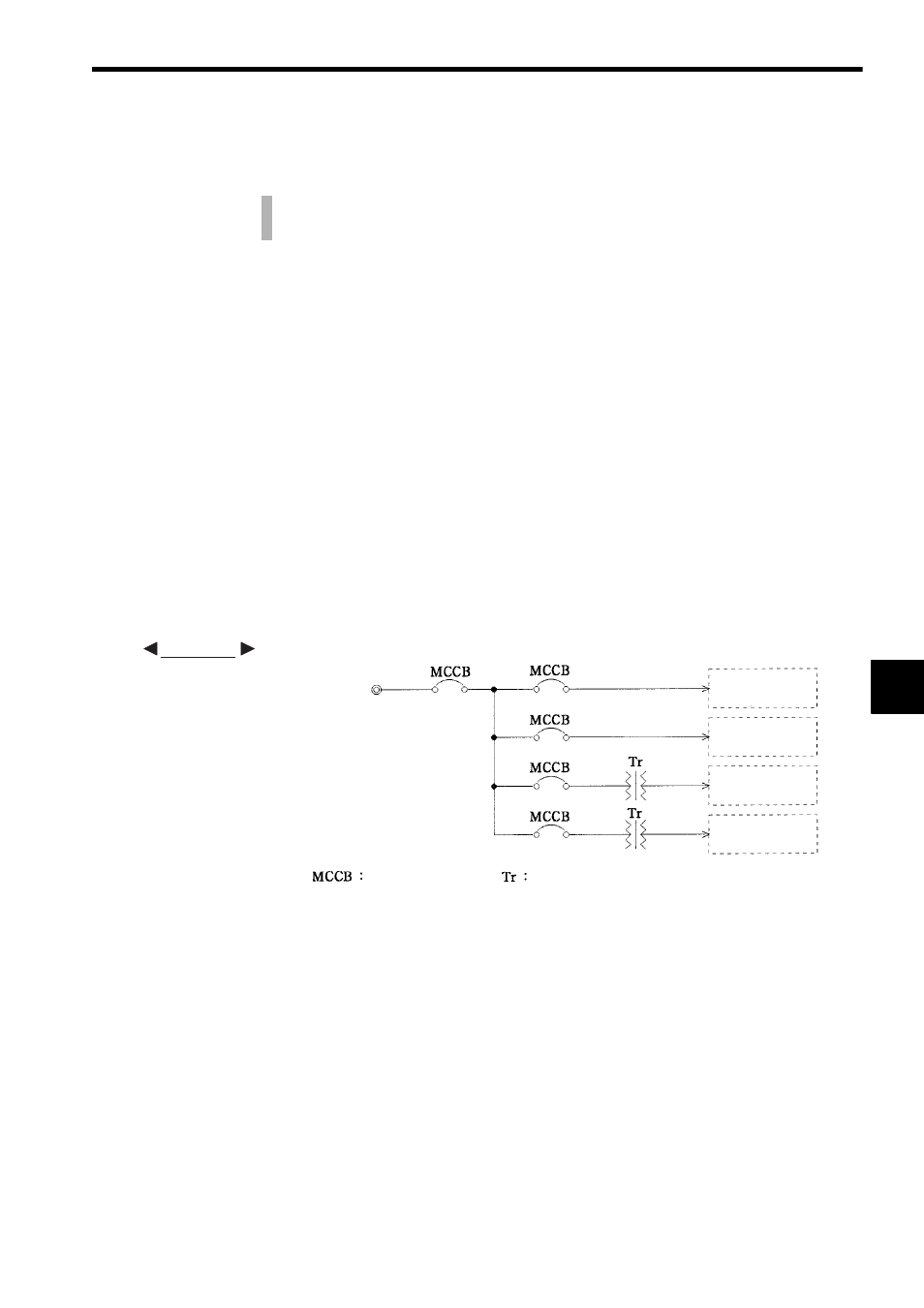
1) The power supply circuits for the GL120 and GL130 can be divided into the following
four systems:
a) Power supply for the Power Supply Module
b) Power supply for I/O circuits
c) Power supply for operation circuits
d) Power supply for main circuits
2) Wire these circuits so that are separated from each other as shown in the following fig-
ure.
This section explains basic wiring procedures and precautions for I/O Modules.
It also explains grounding of Modules.
EXAMPLE
Main circuits
Operation circuits
Power Supply
Module
I/O circuits
Wiring circuit-breaker
Insulation transformer
200 VAC