Yaskawa 120 Series I/O Modules User Manual
Page 169
4 Analog I/O Specifications
4.2.1 Analog Output Modules (
±10 V, 2 channels)
4-22
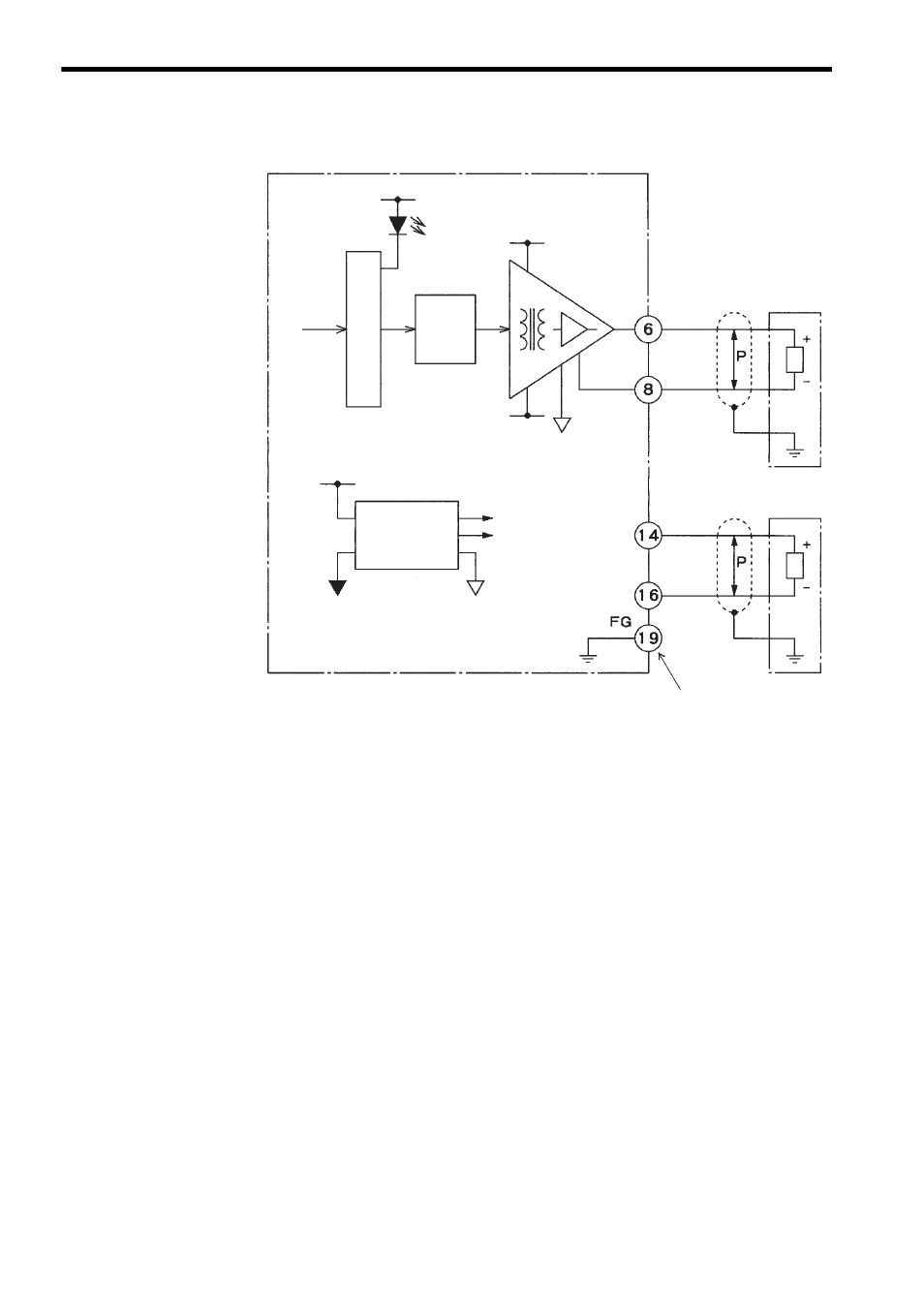
3) The following diagram shows the circuit configuration.
The above circuit configuration is for Modules with a version number of
VER. C or later.
Note: Field Wiring Terminal 19
Connections to field wiring terminal 19 depended on the version of the Module. Be
sure to connect terminal 19 correctly according to the version.
• If the Module is VER. B, terminal 19 is not connected to anything internally.
• If the Module is VER. C or later, terminal 19 is connected through the Module to the Mount-
ing Base. It can thus be used to connect the shield of the shielded twisted-pair wire when ground-
ing at the Module.
The version number of the Module is written on the nameplate on the right side of the Module.
From CPU
Status display
D/A
converter
Isolation amplifier
0 V (analog)
Load
Insulated
DC/DC
converter
0 V (analog)
See Note.
+5 V
-15 V
CH1 +
CH1 -
CH2 +
CH2 -
+15 V
-15 V
0 V
+5 V
Internal circuits