Yaskawa 120 Series I/O Modules User Manual
Page 270
6.4 Precautions on Wiring
6-43
6
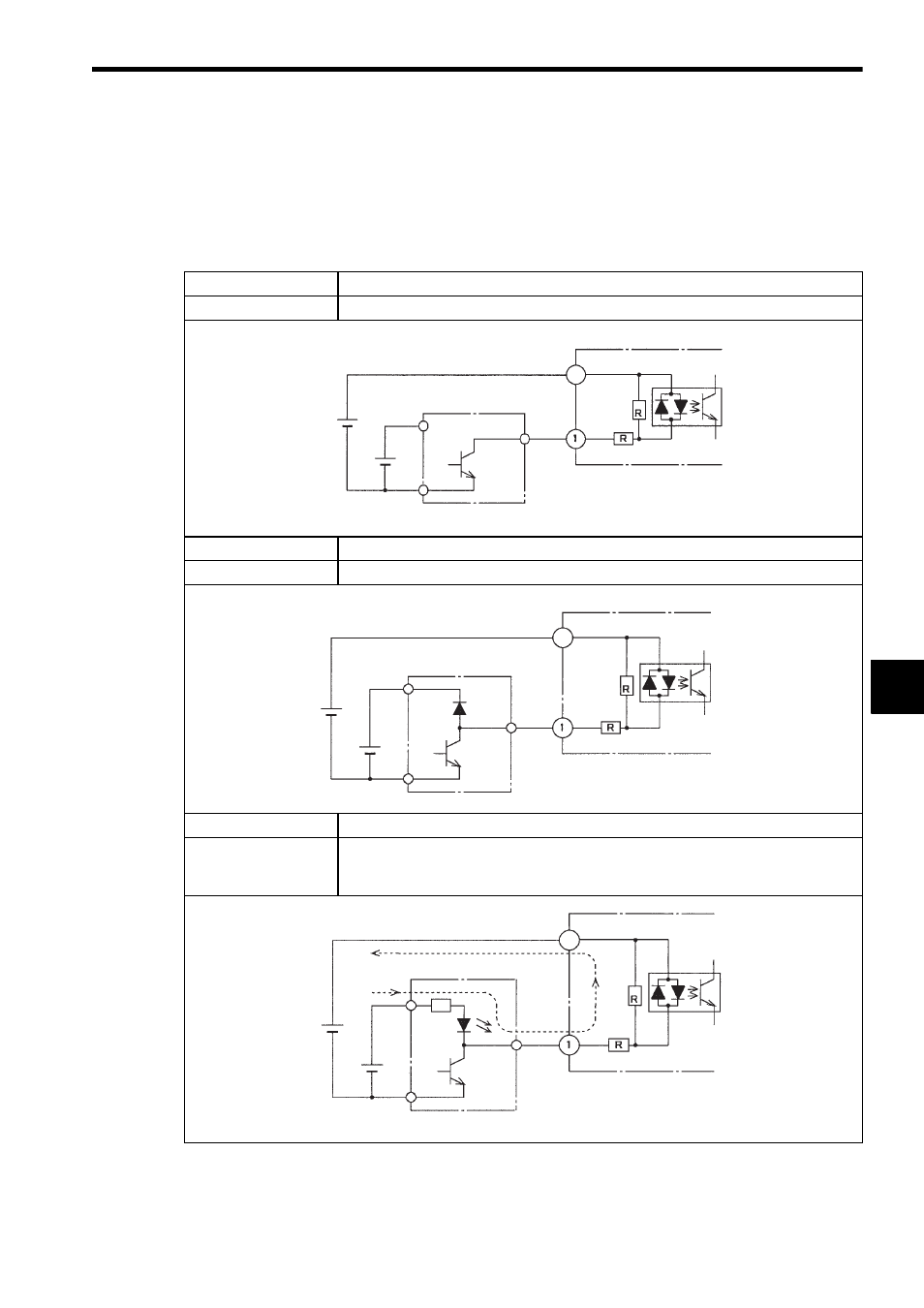
3) Connecting DC Input Devices with Different Voltage Ratings
Normally, the power supply voltage of the input device should match that of the DC
Input Module. The following table shows examples of input devices with different
voltage ratings and advises whether or not they may be connected to the DC Input
Module.
Input Device
Open collector output (V1
< V2)
Connection
Can be connected.
Input Device
Output with a diode (V1
< V2)
Connection
Can be connected.
Input Device
Output with a resistor and LED (V1
< V2)
Connection
Cannot be connected. When the input device is OFF, current indicated by the dot-
ted line in the figure on the left may flow, causing the LED
of the input device to glow dimly.
V1: Input signal power supply
V2: Input device power supply
DC Input Module
+Common 1
Photocoupler
Input
Input device
V1
24 VDC
V2
48 VDC
9
V1: Input signal power supply
V2: Input device power supply
DC Input Module
+Common 1
Photocoupler
Input
Input device
V1
24 VDC
V2
48 VDC
9
V1: Input signal power supply
V2: Input device power supply
DC Input Module
+Common 1
Input
Photocoupler
Input device
V1
24 VDC
V2
48 VDC
9