7) connecting solenoids with diodes – Yaskawa 120 Series I/O Modules User Manual
Page 266
6.4 Precautions on Wiring
6-39
6
Here, a dummy resistor can be connected in parallel with the input load to correct
the problem.
Assuming that the load will operate properly with a leakage current of 1.5 mA or
less, then the value of the dummy resistor R can be computed as follows:
Thus, the value for R should be 6 k
Ω or less.
If the resistance is too small, the amount of heat generation will increase, and a high
wattage will be required. Here, we will compute the wattage for a dummy resistor of
6 k
Ω.
Normally, about three times the computed value is used to allow surplus wattage.
A 5-W resistor would thus be used.
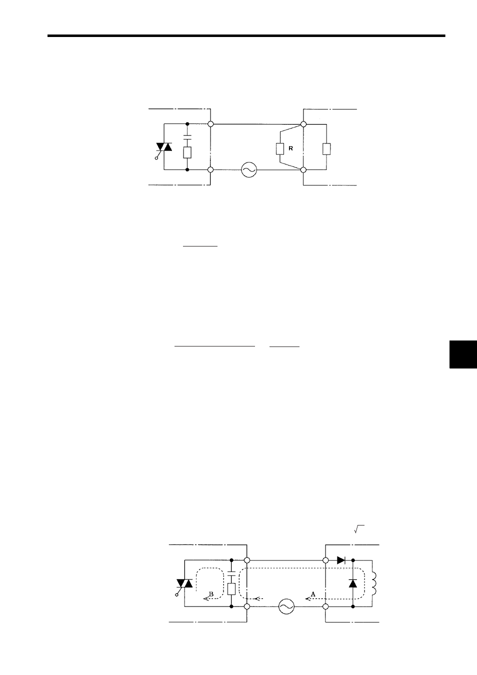
7) Connecting Solenoids with Diodes
Some solenoids used as the load of the AC Output Module may contain built-in
diodes.
Solenoids with diodes have an advantage in that they are driven by half-wave recti-
fication and thus require a lower activation current.
Abide by the following precautions when such diodes are used as a load for an AC
Output Module.
a) Overvoltage can be applied to the load when the output is OFF. The rectifying diode
must therefore be able to withstand a reverse voltage of 2
E or greater.
Fig. 6.19 Solenoids with Diode (1)
AC Output Module
Load device
Output
Dummy
resistor
Load impedance
ZL
Common
Load power supply
(100/200 VAC)
∴
R < 6 k
Ω
3 mA
× < 1.5 mA
R
R + 6 k
Ω
W = = = Approx. 1.7 W
(Power supply voltage)
R
2
(100 V)
6 k
Ω
2
2
AC Output Module
Solenoid
Output
Rectifier diode
Leakage current = 5 mA
Flywheel
diode
Common
Load power supply
(100/200 VAC)