5) relay contact 16-point output modules – Yaskawa 120 Series I/O Modules User Manual
Page 298
8.1 EN Standard Compliant I/O Modules
8-11
8
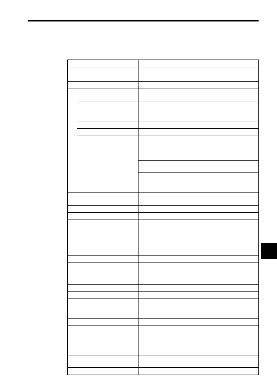
5) Relay Contact 16-point Output Modules
Table 8.6 Specifications of Relay Contact 16-point Output Modules
Item
Specification
Name
Relay Contact 16-point Output Module
Model Name
RELAY-16P
Model No.
JAMSC-120DRA84309 (EN standard)
C
ont
act S
peci
fica
tions
Rated Voltage/Current
240 VAC, 1 A, resistive load
24 VDC, 1 A, resistive load
Maximum Load Power
750 VA (AC loads)
90 W (DC loads)
Maximum Load Voltage
264 VAC/125 VDC
Minimum Load Voltage/Current 100 mVDC, 0.1 mA
Contact Resistance
100 m
Ω max.
Contact
Life
Electrical
3 A at 30 VDC, resistive load:100,000 operations min.
1 A at 30 VDC, resistive load: 300,000 operations min.
τ = 7 ms:
150,000 operations min.
τ = 40 ms: 40,000 operations min.
1 A at 120 VAC, cos
φ = 1.0: 400,000 operations min.
cos
φ = 0.4: 250,000 operations min.
1 A at 240 VAC, cos
φ = 1.0: 300,000 operations min.
cos
φ = 0.4: 200,000 operations min.
Mechanical
20 million operations min.
Output Delay Times
OFF to ON: 10 ms max.
ON to OFF: 15 ms max.
Output Type
Relay contact outputs
Number of Commons
2
Number of Outputs per Common
8 points/common
Output Power Supply per Common
a) When using an AC power supply (100 to 120 VAC or 200 to
240 VAC), connect Power supplies with the same phase to
the common 1 and common 2.
b) Do not connect AC power supply and DC power supply to
one common.
External Connections
Removable terminal block with M3 screw terminals
Output Protection Type
Unprotected outputs (according to IEC1131-2)
Builtñin Fuse
None
Surge Suppressor
None
Other Output Protection
None
Number of Outputs
16
Output Signal Indication
Indicator for each point; lit when the output is ON.
Status saved in internal logic.
Status Indication
ACTIVE: Lit during output processing
Insulation Method
Relay
Dielectric Strength
1,500 VAC for 1 min or 1,800 VAC for 1 s between output termi-
nals and internal circuits and between all output commons
Insulation Resistance
100 M
Ω min. at room temperature and humidity between out-
put terminals and ground (measured by a 500-VDC test voltage
megohmmter)
External Power Supply
100 to 120-VAC or 200 to 240-VAC or 24 VDC supplied to drive
loads
Derating Conditions
None