7 64-point output modules, 1) purpose of i/o allocation, 2) module type setting – Yaskawa 120 Series I/O Modules User Manual
Page 131: 3) i/o reference number setting
3.4 I/O Allocation
3-101
3
3.4.7
64-point Output Modules
1) Purpose of I/O Allocation
The relationship between I/O signals and I/O references must be defined so that the
CPU Module can input signals from input devices and output signals to output
devices. The following settings are necessary to define this relationship for Digital
Output Modules.
(1) Module Type
(2) I/O Reference Numbers
(3) I/O Data Format
Setting these items is performed in a process called I/O allocation. I/O allocation is
performed using the MEMOSOFT and the settings are recorded in the I/O allocation
tables stored in memory in the CPU Module.
Refer to the following manuals for specific setting procedures.
• MEOCON GL120, GL130 MEMOSOFT for P120 Programming Panel User’s
Manual (Manual No. SIEZ-C825-60.7), Chapter 7 Setting System Configuration.
• MEMOCON GL120, GL130 MEMOSOFT for DOS User’s Manual (Manual No.
SIEZ-C825-60.10), Chapter 7 Setting System Configuration.
• MEMOCON GL120, GL130 MEMOSOFT for Windows User’s Manual (Manual
No. SIEZ-C825-60.25), Chapter 6 Setting the Module Configuration.
2) Module Type Setting
The type of Output Module mounted in the slot is set as the Module type. Only the
last 11 alphanumeric characters of the model number are necessary. For example
120DDO36410 is the Module type for the JAMSC-120DDO36410.
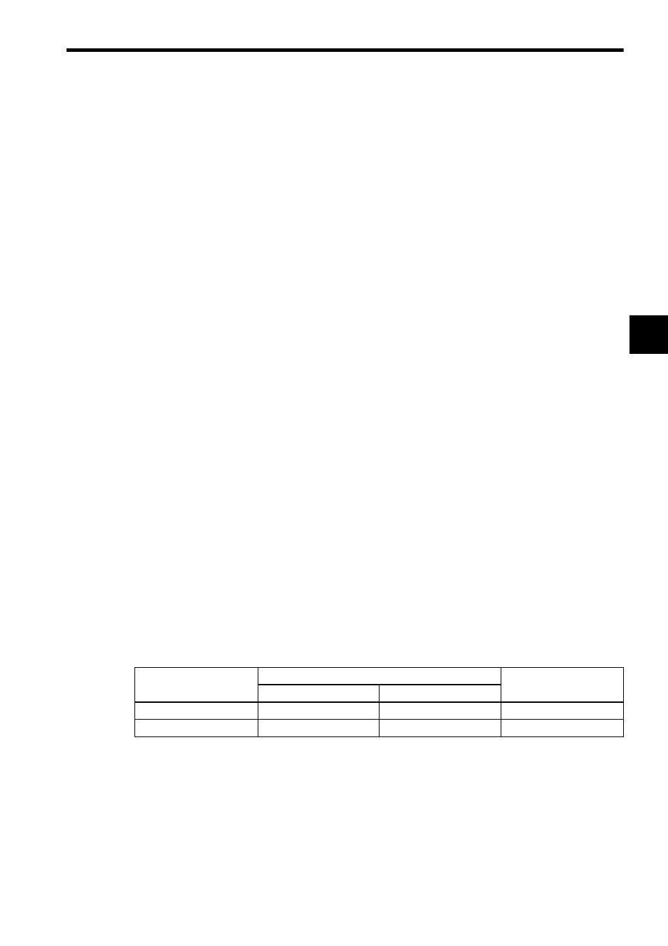
3) I/O Reference Number Setting
(a) The leading I/O reference number used by the Output Module is set.
(b) Any one of the I/O reference numbers and points listed in the following table
can be set.
Type of Input
References for I/O Allocation
Points/Registers
CPU10, CPU20, CPU21
CPU30, CPU35
Output coils
000001 to 001024
000001 to 004096
64 points
Output registers
400001 to 400512
400001 to 400512
4 registers