1 installing modules, 1 module installation location, 1) module installation loacation – Yaskawa 120 Series I/O Modules User Manual
Page 229: 2) module installation location on mounting base
6 Installation and Wiring
6.1.1 Module Installation Location
6-2
6.1
Installing Modules
6.1.1 Module Installation Location - - - - - - - - - - - - - - - - - - - - - - - - - - - - - - 6-2
6.1.2 Installing I/O Modules with Terminal Blocks - - - - - - - - - - - - - - - - - - - 6-4
6.1.3 Installing I/O Modules with Connectors - - - - - - - - - - - - - - - - - - - - - 6-10
6.1.1
Module Installation Location
1) Module Installation Loacation
Install the following Modules on a Mounting Base. The mounting procedures for
installing I/O Modules and Special Purpose Modules on the Mounting Base are
described in 6.1.2 Installing I/O Modules with Terminal Blocks and 6.1.3 Installing
I/O Modules with Connectors.
• Power Supply Modules
• CPU Modules
• Communication Modules
• I/O Modules
• Special Purpose Modules
• Motion Modules
• Expander Modules
2) Module Installation Location on Mounting Base
The following table shows the Module installation location on the Mounting Base.
This section describes how to install Modules on a Mounting Base in the control
panel.
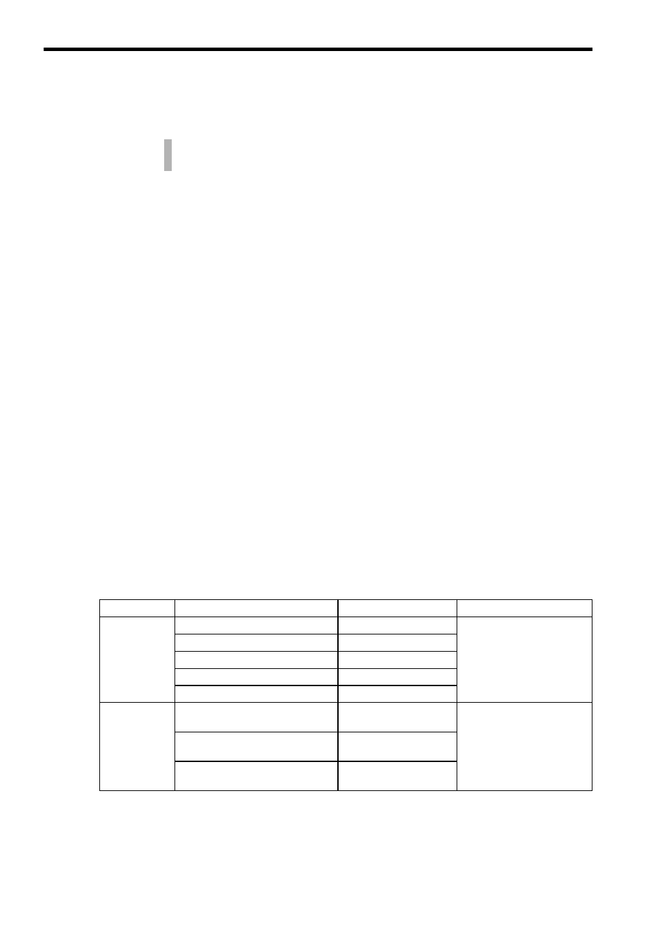
Table 6.1 Module Installation Location on Mounting Base
Product
Name
Model No.
Installation Location
Digital Input
Modules
100-VAC 16-point Input Module
JAMSC-120DAI54300
Any rack on the Mounting
Base
200-VAC 16-point Input Module
JAMSC-120DAI74300
12/24-VDC 16-point Input Module
JAMSC-120DDI34300
12/24-VDC 32-point Input Module
JAMSC-120DDI35400
12/24-VDC 64-point Input Module
JAMSC-120DDI36400
Analog Input
Modules
Analog Input Module
(
±10V, 4 channels)
JAMSC-120AVI02000
Any rack on the Mounting
Base
Analog Input Module
(0 to 10V, 4 channels)
JAMSC-120AVI02100
Analog Input Module
(0 to 20 mA, 4 channels)
JAMSC-120ACI02000