Yaskawa 120 Series I/O Modules User Manual
Page 202
5 Register I/O Specifications
5.1.1 Register Input Modules
5-4
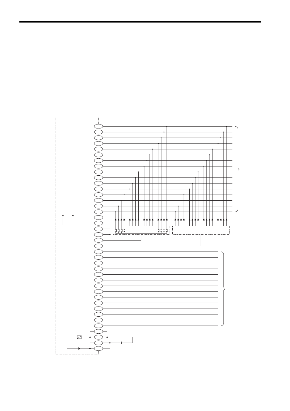
Note: (1) The following pins of CN1 are internally connected:
A1 and B1, A2 and B2, A11 and B11
Also, connect them externally. Not connecting these pins externally may cause
malfunction of GL120 and GL130.
(2) The pin A12 and B12 are not connected.
(3) External connection connector (included)
Connector: FCN-361J040-AU (soldered) (made by Fujitsu Ltd.)
Cover: FCN-360C040-B (made by Fujitsu Ltd.)
(4) Recommended wires
Use 0.26 mm
2
(AWG23) wires for connections between the connector pins.
3) The following diagram shows an example of external connections.
Note: External connection cable
The cable type W5410 for 64-point I/O Modules are available for external connec-
tion cables. For the details, refer to 3.3 I/O Module Cables.
B20
DATA 2
DATA 3
4
×10
0
(2
2
)
DATA 1
DATA 4
DATA 5
DATA 6
DATA 7
DATA 8
DATA 9
DATA 10
DATA 11
DATA 12
DATA 13
DATA 14
DATA 15
DATA 16
SEL 1
SEL 2
SEL 3
SEL 4
SEL 5
SEL 6
SEL 7
SEL 8
SEL 9
SEL 10
SEL 11
SEL 12
SEL 13
SEL 14
SEL 15
SEL 16
1
×10
0
(2
0
)
2
×10
0
(2
1
)
8
×10
0
(2
3
)
1
×10
1
(2
4
)
2
×10
1
(2
5
)
4
×10
1
(2
6
)
8
×10
1
(2
7
)
1
×10
2
(2
8
)
2
×10
2
(2
9
)
4
×10
2
(2
10
)
8
×10
2
(2
11
)
1
×10
3
(2
12
)
2
×10
3
(2
13
)
4
×10
3
(2
14
)
8
×10
3
(2
15
)
SELECT 2
SELECT 1
SELECT 3
SELECT 4
SELECT 5
SELECT 6
SELECT 7
SELECT 8
SELECT 9
SELECT 10
SELECT 11
SELECT 12
SELECT 13
SELECT 14
SELECT 15
SELECT 16
+ -
A group of
contact points
BCD
Binary
Signals
0.5-A Fuse
12/24 VDC
A group of contact points
To other
group of
contact
points
To other
group of
contact
points
A20
B19
A19
B18
A18
B17
A17
B16
A16
B15
A15
B14
A14
B13
A13
B12
A12
B11
A11
B10
A10
B9
A9
B8
A8
B7
A7
B6
A6
B5
A5
B4
A4
B3
A3
B2
A2
B1
A1