Caution – Yaskawa 120 Series I/O Modules User Manual
Page 201
5.1 Register Input Specifications
5-3
5
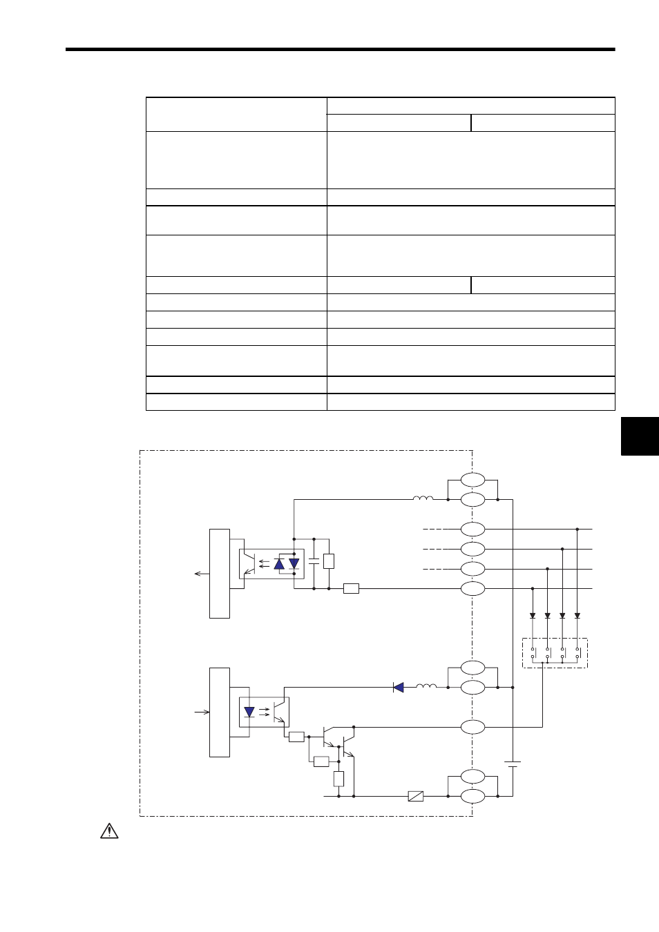
2) The following diagram shows the circuit configuration.
Do not replace the built-in fuses of the Register I/O Modules.
If the built-in fuses are replaced by anyone other than a Yaskawa-approved
technician, a failure or malfunction may occur in the Register I/O Modules, and
the guarantee is void.
Status Indication
R: Lights while the Module is operating normally.
ACTIVE: Lights during input output processing.
F: Lights when the fuse is blown out or the output power supply
is disconnected.
Insulation Method
Photocoupler
Dielectric Strength
1,500 VAC for 1 min or 1,800 VAC for 1 s between the input out-
put terminals and the internal circuits.
Insulation Resistance
100 M
Ω min. at room temperature and humidity between the
input output terminals and the ground (measured with a 500
VDC test voltage megohmmeter).
External Power Supply
12 VDC supplied to signals
24 VDC supplied to signals
Derating Conditions
None
Internal Current Consumption
150 mA max. at 5 VDC
Maximum Heat Value
3.5 W
Hot Swapping
(Removal/insertion under power)
Permitted
Approx. Mass
300 g
External Dimensions
40.3
×130×103.9 mm (W×H×D)
Item
Specifications
At 12 VDC
At 24 VDC
0V
DATA4
DATA3
DATA2
DATA1
To CPU
From CPU
Internal circuits
Internal circuits
Photo-
coupler
Photo-
coupler
INCOMM
Fuse
Contact points
3.3k
Ω
+12/24V
SEL1
12/24VDC
-
+
A11
B20
A20
B19
A19
B11
A1
B1
B10
A2
B2
Connector CN1
Pin No.
CAUTION