Yaskawa 120 Series I/O Modules User Manual
Page 175
4 Analog I/O Specifications
4.2.2 Analog Output Modules (0 to 10 V, 2 channels) (0 to 5 V, 2 channels)
4-28
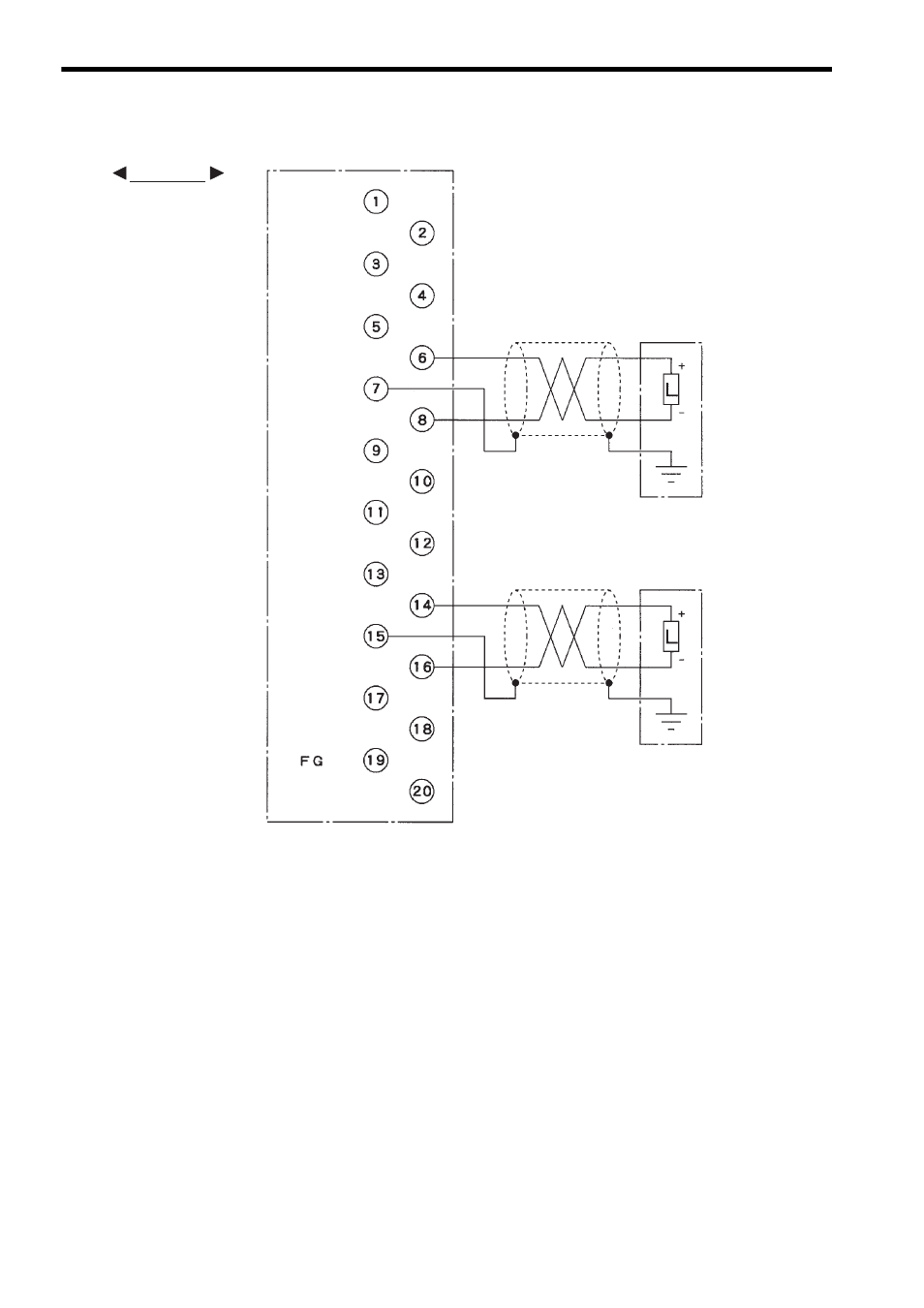
4) The following diagram shows an example for terminal connections.
Note: (1) Isolation between Output Channels
All the channels of the output circuit are isolated each other.
(2) Recommended Cables
Use shielded twisted-pair wires of 1.3 mm
2
(AWG16) to 0.5 mm
2
(AWG20) to
connect to the terminal block.
(3) One-point Shield Connection
As a rule, connect the shield at one point on the load side. However, better out-
put characteristics may be obtained by connecting it at one point on the Module
side rather than on the load side, so consider which way is better depending on
the actual situation. An incorrect connection will make input signal unstable and
cause malfunction.
(4) Grounding the Module
The FG terminal of the Module is connected to the Mounting Base via the Mod-
ule. When grounding on the Module side, use the FG terminal. The “Not con-
nected” terminals are not connected inside the Module. Use them as relay
terminals.
(5) Crimp Terminals
Use M3 terminals for crimping to the terminal block.
(6) Unconnected Terminals
Terminals 1 to 5, 7, 9 to 13, 15, 17, 18 and 20 are not connected.
Not connected
Not connected
Not connected
Shielded twisted-pair wire
External device
External device
Not connected
Not connected
Not connected
Not connected
Not connected
Not connected
Not connected
Not connected
Not connected
Not connected
Not connected
Not connected
0 to 10 V
0 to 10 V
Shielded twisted-pair wire
CH2 -
CH2 +
CH1 -
CH1 +
EXAMPLE