Important – Yaskawa 120 Series I/O Modules User Manual
Page 126
3 Digital I/O Specifications
3.4.5 16-point Output Modules
3-96
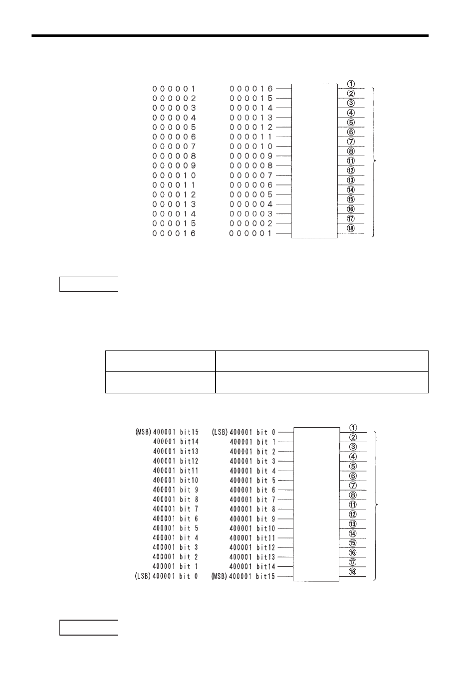
Fig. 3.9 Allocation of Output Coils
When allocating output coils, the MEMOSOFT is set by default to “MSB.”
When output coil allocation is set to “MSB,” the leading reference number is allocated
to the smallest output number (output 1) on the Output Module.
(2) When output register 400001 is allocated, the bit order can be set to either
“MSB” or “LSB,” as described in the following table and shown in the illustration
below it.
Refer to Fig. 3.10 Allocation Output Registers for details.
Fig. 3.10 Allocation Output Registers
When allocating output registers, the MEMOSOFT is set by default to “LSB.”
When output register allocation is set to “LSB,” bit 15 (MSB) of the output register is
allocated to the smallest output number (output 1) on the Output Module.
Terminal number
Output signals
Output 1
MSB Setting
LSB Setting
Output 2
Output 3
Output 4
Output 5
Output 6
Output 7
Output 8
Output 9
Output 10
Output 11
Output 12
Output 13
Output 14
Output 15
Output 16
(LSB)
(MSB)
(MSB)
(LSB)
IMPORTANT
Output Register LSB Setting
Bit 15 (MSB) of the output register (400001) is allocated to the
smallest output number (output 1) on the Output Module.
Output Register MSB Setting
Bit 15 (MSB) of the output register (400001) is allocated to the
largest output number (output 16) on the Output Module.
Terminal number
Output signals
LSB Setting
MSB Setting
Output 1
Output 2
Output 3
Output 4
Output 5
Output 6
Output 7
Output 8
Output 9
Output 10
Output 11
Output 12
Output 13
Output 14
Output 15
Output 16
IMPORTANT