Example – Yaskawa 120 Series I/O Modules User Manual
Page 164
4.1 Analog Input Specifications
4-17
4
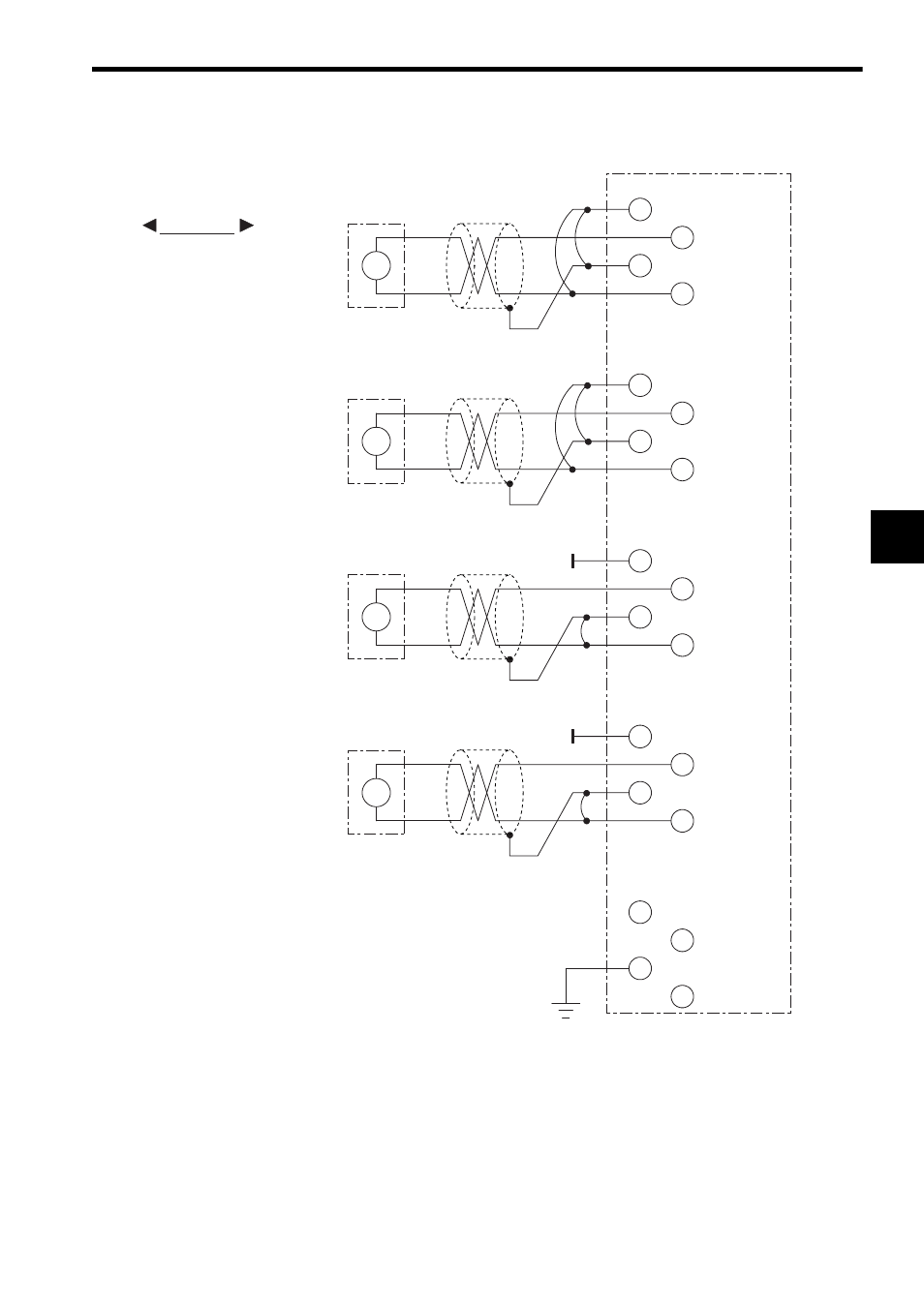
4) The following diagram shows an example for terminal connections.
Note: (1) Isolation between Input Channels
There is no insolation provided between the input circuit channels. If isolation
between channels is required, use a commercial isolation amplifier for each
channel.
(2) Recommended Cables
Use shielded twisted-pair wire 1.3 mm
2
(AWG16) to 0.5 mm
2
(AWG20) to con-
nect to the terminal block.
EXAMPLE
For Current Signal Source
External device
Shielded twisted-pair wire
For Voltage Signal Source
Shield 1
Not connected
Shield 2
Shield 3
Shield 4
Not connected
Not connected
External device
Shielded twisted-pair wire
Shielded twisted-pair wire
Shielded twisted-pair wire
External device
4 to 20 mA
4 to 20 mA
1 to 5 V
1 to 5 V
External device
1
2
3
4
5
6
7
8
9
10
11
12
13
14
15
16
17
18
19
20
CH1 S
CH1 +
CH1 -
CH2 S
CH2 +
CH2 -
CH3 S
CH3 +
CH3 -
CH4 S
CH4 +
CH4 -
FG
A
+
-
A
+
-
V
+
-
V
+
-
Grounding resistance
100
Ω max.