Yaskawa 120 Series I/O Modules User Manual
Page 51
3.1 Digital Input Module specifications
3-21
3
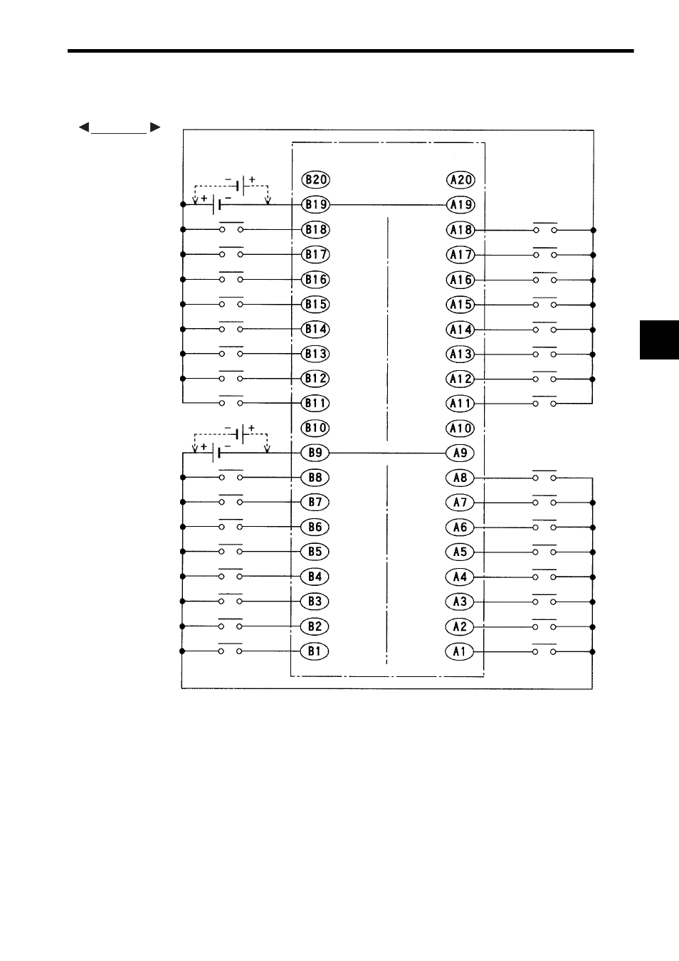
3) The following diagram shows an example of terminal connections.
Note: (1) CN1 pins A9 and B9 and pins A19 and B19 are internally connected. Connect
these pins externally as well. Not connecting them can cause malfunction.
(2) Pins A10, A20, B10, and B20 are not connected.
(3) The polarity of the external power supply for signals can be either positive or
negative.
(4) Connector for External Connections (included)
Connector: FCN-361J040-AU (soldered) (manufactured by Fujitsu Ltd.)
Cover: FCN-360C040-B (manufactured by Fujitsu Ltd.)
(5) Recommended Wires
Use wires of 0.26 mm
2
(AWG23) to connect to each connector pin.
12/24 VDC
CN1 connector
pin numbers
Input 32
Common 2
Input 30
Input 26
Input 24
Input 22
Input 20
Input 18
Input 16
Input 28
Common 2
Input 14
Input 12
Input 10
Input 8
Input 6
Input 4
Input 2
Not
connected
Input 31
Common 2
Input 29
Input 25
Input 23
Input 21
Input 19
Input 17
Input 15
Input 27
Common 1
Input 13
Input 11
Input 9
Input 7
Input 5
Input 3
Input 1
CN1 connector
pin numbers
Not
connected
Not
connected
Not
connected
12/24 VDC
(Continued on next page)
EXAMPLE